2-12
Chapter2
CX6
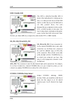
LED1: Standby LED
This LED is called the Stand-By LED. It
shows if the motherboard is in the power on
state, or is fully powered down. If this LED
light is on, that means your motherboard is
not fully powered down. You can't
disassemble any components, add-on cards,
CPU, or RAM modules in this state. You
have to fully check and shutdown the system
power, before this LED will turn off. Only
then can you disassemble any components, add-on cards, CPU, or RAM module.
CD_IN1, CD_IN2 and AUX_IN1:
CD_IN1 & CD_IN2:
These connectors are
for the internal CD-ROM drive audio cable
connection use, and these two connectors
are used for different types of CD audio
cable connectors. Please check your audio
cable attached with the CD-ROM drive to
see which type connector you have, then
plug it to the appropriate connector on the
motherboard.
AUX_IN1:
This connector is used for other internal audio cable connections. For example,
if you have installed two internal CD-ROM drives in your computer system, you can
connect a secondary CD-ROM drive audio cable to this connector.
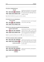
CCMOS1: CMOS Discharge Jumper
Jumper CCMOS1 discharge CMOS
memory. When you install the motherboard,
make sure this jumper is set for normal
operation (pin 1 and 2 shorted). See figure
2-7.
Содержание AB-CX6
Страница 2: ......
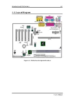
Страница 13: ...Introduction of CX6 Features 1 9 User s Manual 1 3 Layout Diagram Figure 1 1 Motherboard component location ...
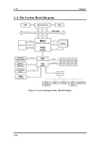
Страница 14: ...1 10 Chapter1 CX6 1 4 The System Block Diagram Figure 1 2 System diagram of the Intel 820 chipset ...
Страница 78: ...3 44 Chapter3 CX6 ...
Страница 84: ...B 4 Appendix B CX6 ...
Страница 90: ...D 4 Appendix D CX6 ...
Страница 96: ...E 6 Appendix E CX6 ...
Страница 104: ...G 4 Appendix G CX6 ...
Страница 110: ...H 6 Appendix H CX6 ...


