


5 Final Assembly
56
SA11
SA21
TC_00148
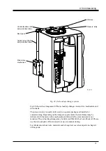
Fig. 42c.
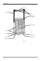
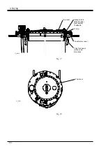
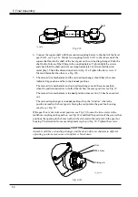
6. Connect the square shaft with the mounted coupling halves to the shaft of the bevel
gear SA21, see Fig. 42c. Mount two coupling halves SA11 to the other end of the
square shaft and to the shaft of the bevel gear on the on-load tap-changer. Push the
shaft to the bottom of the fitting in the coupling halves. Tighten light the screws
and check that the shaft can be moved approximately 2 mm in axial direction
(axial play). Check the dimension shown in Fig. 41e. Tighten the two screws A
first and thereafter the other, see Fig. 41h.
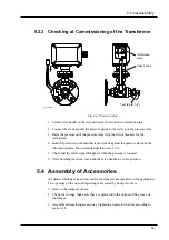
7. The motor-drive mechanism and the on-load tap-changer should have the same
indicated tap position and be in their
exact
positions.
The motor-drive mechanism and on-load tap-changer are in the same position
when the position indicators in both of them show the same position, see Fig. 39.
The motor-drive mechanism is in
exact
position since section 5.2 has been carried
out.
The on-load tap-changer is in
exact
position when the window where the
position is read in the bevel gear is facing the red point in the gear box housing
exactly, see Fig. 39.
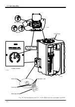
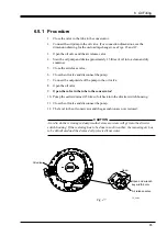
If the gear box is not in its exact position, see Fig. 39, loosen the two screws in the
multihole coupling on the gearbox, see Fig. 42d, and find the position of the screws that
positions the opening in the brass toothed wheel closest to the red point in the gear box
housing. The deviation from exact alignment is given in Fig. 39. Tighten the screws.
CAUTION
Assembly with the on-load tap-changer and the motor-drive mechanism in different
operating positions may cause a transformer break down.
Fig. 42d.
Driving pin
TC_00150
M8 screw
Disc


