


4 Drying
45
3. If a tie-in resistor from ABB is supplied, its screw joints are to be retightened
(tightening torque 15 Nm) and locked by the method specified by the transformer
manufacturer for similar screw joints.
4. If the tap selector has supporting plates these should also be retightened and locked
by method specified by the transformer manufacturer for similar screw joints.
(Only tap selector IV in reinforced design).
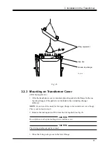
4.3 Installation of Diverter Switch
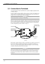
When yoke-mounted, carry out section 3.2.3 before installing the diverter switch.
CAUTION
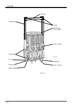
Check the serial numbers to make sure that the diverter switch is mounted in the
correct housing, see Fig. 34.
CAUTION
Make sure that the diverter switch housing is clean and free from water and that no
foreign objects (tools etc.) are left in the housing.
CAUTION
Lower the diverter switch into its housing carefully so that neither the diverter switch
nor the housing are damaged.
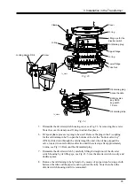
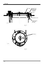
The diverter switch is provided with guiding slots on opposite sides that fit against the
guiding bars in the diverter switch housing, see Figs. 34 and 35.
Rotate the diverter switch so the widest slot is aligned with the widest guiding bar, see
Figs. 34 and 35.
When the diverter switch is lowered, check visually that its plug-in contacts are aligned
with the contacts in the cylinder wall.
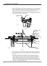
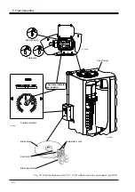
The top part of the diverter switch lifting device should be at least 1 mm under the level
of the machined surface of the upper flange, see Fig. 36 when lowered to its final
position. If not, push the diverter switch down to its final position.
In order to ensure that the diverter switch pin has engaged the coupling disc, carry out
at least
three
tap change operations in
one
direction. A distinct sound is heard
when the diverter switch operates which indicates that the driving pin of the diverter
switch has been connected.
Insert the O-ring for the cover in the upper flange. Mount the on-load tap-changer
cover. Turn the cover so the guiding pin in the housing is facing the guiding hole in the
cover. (The cover has to be pressed down in order to overcome the spring force of the
springs that hold the diverter switch pressed in place.) Insert screws and washers and
tighten them.


