


3 Installation in the Transformer
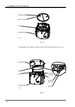
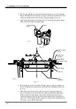
4. Place the upper flange over the opening in the transformer cover. Turn the upper
flange so the flange for the bevel gear is aligned with the driving shaft. The screws
in the lower flange shall fit into the holes in the upper flange, see Fig. 28.
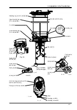
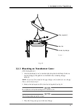
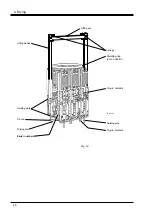
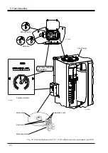
5. Apply the lifting equipment according to Fig. 27 and lift the on-load tap-changer
slowly until it just touches the upper flange.
38
Fig. 27.
6. When the flanges touch, mount thirty M8 nuts, spring washers and washers, see
Fig. 28. Tightening the nuts alternately until fully home. Retighten all nuts with
24.5 Nm.
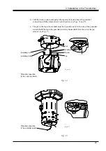
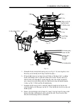
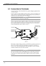
7. Place the O-ring of the bevel gear unit in its groove in the upper flange, see
Fig. 29. Remount the bevel gear unit in the position it had before dismantling
(make sure the pin in the bottom of the gearbox fits into the hole in the top
section) and make sure that the pin in the vertical shaft end fits into the driving
shaft slot, without rotating the driving shaft. Fix the gear unit in the flange by its
four clamps screws M8x20 and washers.
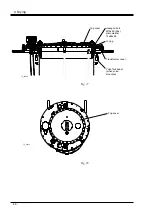
Lower flange
Yoke fork
Lifting
equipment
Gasket in lower
flange
Fig. 26.
Locking device
DS 4
TC_00205
Screw
Transformer cover
Gasket (not
included)
Upper flange
TC_00066


