


21
3 Installation in the Transformer
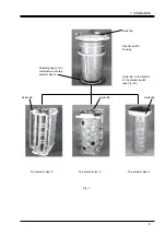
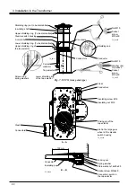
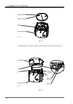
Transport locking
(to be removed)
TC_00191
Screw (to be removed)
Lifting eyes with
fasteners (to be removed)
Fig. 6.
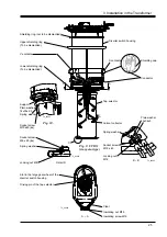
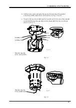
9. Lift the diverter switch housing in position and fit the tap selector to the diverter
switch housing, see Fig. 4. The tap selector driving pin shall fit into the large gear
wheel slot, see Fig. 7, A-A.
CAUTION
The driving crank on the tap selector must not be moved more than slightly to engage
the slot in the large gear wheel of the diverter switch housing.
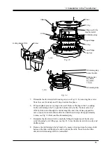
10. Insert four M12x110 screws, two M12x40 and spring washers, see Fig. 7, through
the selector upper part to the six supports of the diverter switch housing. Tighten
the screws.
WARNING
The diverter switch housing and the tap selector contains moving parts. Be
cautious!
11. Connect the supplied conductors between the diverter switch housing and tap
selector, see Fig. 7. The conductor ends and their connecting points have the same
markings. Fasten the conductors with cleats, see Fig. 7, A-A. The number of
conductors is varying depending on rated through current and the type of
connection.
12. If the impulse withstand voltage to earth exceeds 380 kV, insulate the connections
on the tap selector by winding paper around them to a thickness of approximately
3 mm, see Fig. 7, B-B. The paper shall be of the same quality as used for
insulation of conductors within the active part of the transformer.
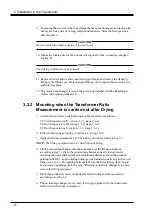
13. If the impulse withstand voltage to earth exceeds 380 kV, mount the supplied
shielding rings (DS 10) at the bottom of the tap selector, see Fig. 7.
CAUTION
After mounting the shielding ring the on-load tap-changer must not stand on the
shieldning ring.
14. Continue with section 3.3


