


62
…6
CONFIGURATION – ADVANCED LEVEL
6.2.4
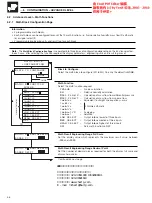
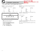
Mass Flow 1 and 2
The two types of mass flow calculations available are as follows:
Mass Flow 1
– uses a volume flow input as the basis for the calculation
Mass Flow 2
– uses a differential pressure input as the basis for the calculation.
The standard formula for mass flow 1 is as follows:
M = k V
P
Tr
Pr
T
where:
k = Scaling constant
V = Input a (input from volume flow source)
P = Absolute Pressure (pressure input source)
T = Temperature (temperature input source)
Tr = Reference temperature (set as a constant)
Pr = Absolute reference pressure (set as a constant).
The temperature units used by the input source must be specified as all calculations use absolute temperatures and conversion is
made if the input uses
C or
F.
The formula used for mass flow 2 is as follows:
(i)
M = k
h
P
Tr
T
Pr
where:
h = differential pressure head
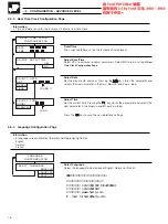
Some differential pressure sensors incorporate a square root linearizer and therefore produce an output linear to flow. In these
instances no additional linearization within the advanced process recorder is required. Where the input from the differential pressure
sensor is linear to differential pressure head the square root linearizer within the advanced process recorder’s
Analogue Input
Configuration Page
must be used.
The formula used internally is:
(ii)
M = k a
P
Tr
T
Pr
where:
input a = linearized flow signal.
The linearized flow signal is produced by the transmitter or derived from the signal linearized within the advanced process recorder.
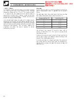
When using mass flow, care must be taken in sizing the differential transmitter. Variations in pressure and temperature affect the
differential pressure developed across the flow device. In its basic form:
M = h
P
T
Note.
As pressure P decreases, the dp(h) increases. Likewise, as temperature T increases this also causes an increase in
dp(h). If the variation in temperature pressure is sufficient to cause the dp to exceed the range of the dp transmitter, then
errors occur in calculating the mass flow. It is therefore generally recommended to size the flow system on minimum pressure
and maximum temperature conditions to ensure the dp transmitter remains within its calibrated range.


