


46
MODULE TYPE
3 Relay
1 RELAY O/P SOURCE
1 O/P POLARITY
POSITIVE
NEGATIVE
2 RELAY O/P SOURCE
2 O/P POLARITY
3 RELAY O/P SOURCE
3 O/P POLARITY
TOTAL COUNT
TOTAL WRAP
PAPER OUT ALARM
I/P FAILURE
DIGITAL I/P
CHART SPEED
LOGIC EQN
POWER FAILURE
REAL TIME ALM
PROCESS ALARM
NONE
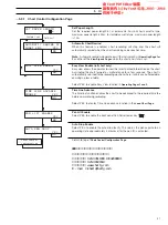
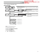
MODULE
CONFIGURATION
Select Digital Output
Digital Source
Polarity Selection
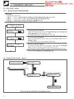
Relay B 1
B 2
B 3
Module Position
Output No.
Total Count
Total Wrap
Paper Out Alarm
Input Failure
Digital Input DA1
Chart Speed
Logic Equation
Power Failure
Real Time Alarm
Process alarm
None
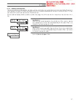
Source State
Source State
Source State
Process Alarm A3
Active
Process Alarm A3
Inactive
Positive
Negative
Positive
Negative
Energized
Energized
De-energized
De-energized
Process Alarm A3
Active
Process Alarm A3
Inactive
NC
C
NO
NO
NC
C
NC
C
NO
NC
C
NO
NC
C
…5
CONFIGURATION – BASIC LEVEL
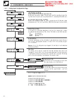
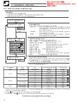
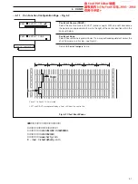
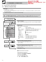
5.4.3
Output Module Configuration Page – Relay Modules
Module Type
The type of module fitted is displayed.
NOT
FITTED
is displayed where the
module location is not used.
The Relay Output module contains three relay output circuits.
Circuit 1 Relay Output Source
Select the source required to activate the relay output:
TOTAL COUNT
– Totalizer pulse output (T1 to T6)
TOTAL WRAP
– Wrap-around of a totalizer (T1 to T6)
PAPER OUT ALARM
– End of chart reached
I/P FAILURE
– Failure of analog input (A1 to A6, B1 to B6)
DIGITAL I/P
– Active digital input (DA1 to DG3)
CHART SPEED
– Selection of chart speed (1 to 3)
LOGIC EQN
– Logic equation true (1 to 10)
POWER FAILURE
– After power failure
REAL TIME ALM
– Real time alarm on (1 or 2)
PROCESS ALARM
– Pre-defined process alarm (A to M, excluding I)
NONE
– No output source required
Circuit 1 Output Polarity
Select the output polarity required:
POSITIVE
– relay energized when condition is true
NEGATIVE
– relay de-energized when condition is true
Circuit 2 Relay Output Source
Select the source required to activate the relay output as for circuit 1 above.
Circuit 2 Output Polarity
Select the output polarity required as for circuit 1 above.
Circuit 3 Relay Output Source
Select the source required to activate the relay output as for circuit 1 above.
Circuit 3 Output Polarity
Select the output polarity required as for circuit 1 above.
Return to top of
Output Module Configuration Page
.


