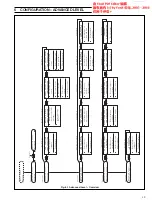
35
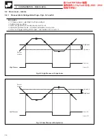
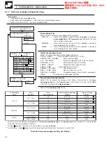
SCALE
ADJUSTMENT
INPUT TO ADJUST
RESET SCALE ADJUST
NONE
YES
NO
ADJUST OFFSET
ADJUST SPAN
e
l
p
u
o
c
o
m
r
e
h
T
f
o
e
p
y
T
e
l
b
a
C
g
n
i
t
a
s
n
e
p
m
o
C
3
4
8
1
S
B
1
.
6
9
C
M
I
S
N
A
4
1
7
3
4
N
I
D
0
3
.
o
N
t
r
a
P
7
3
9
4
S
B
+
–
e
s
a
C
+
–
e
s
a
C
+
–
e
s
a
C
+
–
e
s
a
C
)
K
(
l
A
-
i
N
/
r
C
-
i
N
n
w
o
r
B
e
u
l
B
d
e
R
w
o
ll
e
Y
d
e
R
w
o
ll
e
Y
d
e
R
n
e
e
r
G
n
e
e
r
G
n
e
e
r
G
e
t
i
h
W
n
e
e
r
G
*
)
E
(
i
N
-
u
C
/
r
C
-
i
N
–
–
–
–
–
–
t
e
l
o
i
V
e
t
i
h
W
t
e
l
o
i
V
*
)
N
(
li
s
i
N
/
li
s
i
r
c
i
N
e
g
n
a
r
O
e
u
l
B
e
g
n
a
r
O
e
g
n
a
r
O
d
e
R
e
g
n
a
r
O
–
–
k
n
i
P
e
t
i
h
W
k
n
i
P
*
)
S
d
n
a
R
(
h
R
-
t
P
/
t
P
e
t
i
h
W
e
u
l
B
n
e
e
r
G
k
c
a
l
B
d
e
R
n
e
e
r
G
d
e
R
e
t
i
h
W
e
t
i
h
W
e
g
n
a
r
O
e
t
i
h
W
e
g
n
a
r
O
*
)
B
(
h
R
-
t
P
/
h
R
-
t
P
–
–
–
–
–
–
y
e
r
G
e
t
i
h
W
y
e
r
G
*
)
T
(
i
N
-
u
C
/
u
C
e
t
i
h
W
e
u
l
B
e
u
l
B
e
u
l
B
d
e
R
e
u
l
B
d
e
R
n
w
o
r
B
n
w
o
r
B
n
w
o
r
B
e
t
i
h
W
n
w
o
r
B
*
)
J
(
n
o
C
/
e
F
w
o
ll
e
Y
e
u
l
B
k
c
a
l
B
e
t
i
h
W
d
e
R
k
c
a
l
B
d
e
R
e
u
l
B
e
u
l
B
k
c
a
l
B
e
t
i
h
W
k
c
a
l
B
*
s
t
i
u
c
r
i
c
e
f
a
s
y
ll
a
c
i
s
n
i
r
t
n
i
r
o
f
e
u
l
B
e
s
a
C
*
)
0
1
7
3
4
N
I
D
(
n
o
C
/
e
F
–
–
–
–
0
1
7
3
4
N
I
D
–
–
d
e
r
/
e
u
l
B
e
u
l
B
e
u
l
B
5
CONFIGURATION – BASIC LEVEL…
…5.1.3
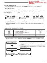
Scale Adjustment Page
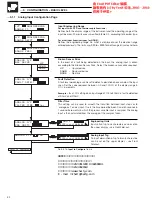
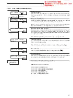
Input to Adjust
Select the analog input to adjust (A1 to A6, B1 to B6, depending on the options
fitted – see Section 4.2). On entry the default is
NONE
.
Scale Adjustment Reset
Select
YES
to reset the analog input offset and span values to their nominal
values.
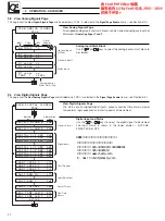
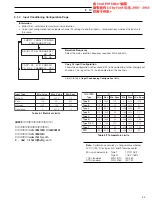
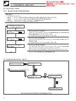
Offset Adjustment
Electrical and resistance thermometer inputs:
apply the correct input for the spot calibration required.
For RTD inputs, use resistance values obtained from standard tables.
Thermocouple inputs:
measure the ambient temperature at the output terminals of the signal source
(calibrator). From thermocouple tables obtain the millivolt equivalent of this
temperature (a) and that for the spot calibration temperature (b). Subtract (a) from
(b) and set the signal source to the resultant value. (The voltage is negative if the
spot calibration temperature is below the measured ambient temperature).
Note.
The displayed units are engineering units.
Set the value required. The decimal point is set automatically.
Example
– if the display range is 50.0 to 250.0 and a spot calibration is required at
100.0 and 225, inject a signal equivalent to 100.0 and set the display to 100.0.
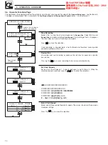
Span Adjustment
Proceed as for
Offset Adjustment
above and apply the correct input for the spot
calibration required. The displayed units are engineering units. Set the value
required. The decimal point is set automatically.
For the example above inject a signal equivalent to 225.0 and set the display to
225.0.
Return to
Input to Adjust
parameter.
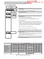
Table 5.3 Thermocouple Compensating Cables

