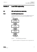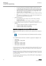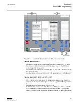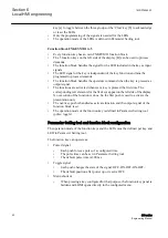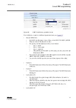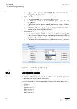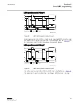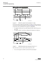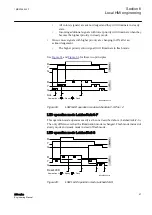
HMI display raster layout and text font selection
The raster in the page changes from symbol presentation to text presentation when a
text object is selected and vice versa.
The text can be presented in two different font sizes:
•
UniCode characters (6 x 12 pixel)
•
UniCode characters (13 x 14 pixel)
The total size of the presented white area (page) represents the visible part of the local
HMI display without header and foot-line.
The visible display for a single line diagram is organized in a raster of 13 x 8 (columns
x rows). Each symbol presented by 24 x 24 pixels included by the drag and drop
method must be dropped in a raster box. The icon
Snap to grid
must be enabled to
place a symbol, for example an apparatus object. The description text for an apparatus
object can be placed in all four directions around the symbol. The description is part
of the symbol and the description can be placed even if the
Snap to Grid
is not enabled.
Handling text
The raster switches when text is selected in a raster of 45 x 15 (columns x rows). One
raster box is the placeholder for one character. A text element must be placed in the
position of the raster. The name and the unit of a measurement or text symbol can be
changed either by double click the symbol or via the object property window.
Select and toggle
Show Texts using the IED Fonts
to get a view how it will look like
later on the real HMI display.
Doing Link to draw lines
The line width has to fit to the line width used for the symbols. The standard size is 2.
Choose the line width in a selection box placed in the upper area above the page. A line
that is not connected to a symbol may be done in any line width in the range 1 - 5. But
it needs to be simple connection points to be drawn.
For the procedure to draw lines when the apparatus symbols are placed, see
Figure
.
1. Place the apparatus or transformer symbols by drag and drop in a raster box.
2. Place the connections symbols by drag and drop in a raster box.
3. Click the
Link
icon to enable direct line drawing.
4. Center the mouse pointer on the center of a connection point; visible in two circles
at the endpoints of a line, to draw a line.
5. Click to start and move the mouse pointer to the destination connection point.
Center once again the mouse pointer and click to drop the line.
6. Draw all line elements that are necessary.
7. Click
Select
in the menu bar to finish the line drawing.
Section 6
1MRS756800 F
Local HMI engineering
92
630 series
Engineering Manual


