5.1.2
Signals and signal management
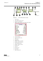
The function block has a set of input and output signals. The placement of function
block signals is from left to right. Input signals are placed on the left and output signals
on the right.
Function blocks can contain more signals than needed in that application part. Unused
signals can be hidden to get a clear picture.
Signals are located up and down on both sides of the middle position. When there is
space left, some signals may be moved up or down for better visibility and connection
routing.
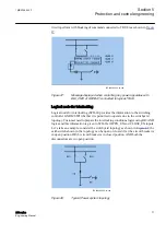
Boolean input and output signals may need to be inverted to fulfil the logic. The
Application Configuration tool supports the adding of inversion logic to a binary
signal.
All input signals have a default value that is used when the signals are not connected
in the configuration.
The input signal on glue logic function blocks can only be inverted if
a glue logic function block with lower execution order in the same
cycle time is available. Similar, the output signal can only be inverted
if a glue logic function block with higher execution order in the same
cycle time is available. Up to two input signals and two output signals
can be inverted for glue logic blocks in the same cycle time.
Even though current is injected to the IED and the IED is connected to
PCM600 in online mode, the signal value in Application
Configuration is shown as zero.
5.1.3
Function block execution parameters
Three function block execution parameters have influence on the runtime execution
of the function block within the application configuration.
•
Execution order
•
Cycle time
•
Instance number
A function block is executed only when at least one of the output
signals is connected.
Each time a new function block is selected these parameters have to be selected. In
fixed mode user selects parameters from the drop down lists in ACT. In automatic
Section 5
1MRS756800 F
Protection and control engineering
56
630 series
Engineering Manual


