6.
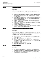
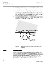
If required, verify the trip time at another voltage. Normally 2 ·
U>Trip
is
selected.
7.
If used, measure the alarm level operating value. Increase the voltage and make
note of the operate value
U>Alarm
. This is done with manual test and without
trip of the test set.
8.
Measure the operating time on the alarm output by connecting the stop of the test
set to an output from
tAlarm
. Inject a voltage 1.2 ·
U>Alarm
and measure the
alarm time.
9.
Check that trip and alarm outputs operate according to the configuration logic.
10. Finally check that start and alarm information is stored in the event menu and if
a serial connection to the SA is available verify that the correct and only the
required signals are presented on the local HMI and on the SCADA system.
Information on how to use the event menu is found in the operator's
manual.
6.3.3.2
Completing the test
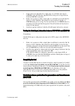
Continue to test another function or end the testing by setting the parameter
TestMode
to
Off
under
Main menu/Tests/IED test mode/TESTMODE:1
. If another function
is tested, then set the parameter
Blocked
to
No
under
Main menu/Tests/Function test
modes/Differential/HZPDIF(87,IdN)/HZPDIF:X
for the function, or for each
individual function in a chain, to be tested next. Remember to set the parameter
Blocked
to
Yes
, for each individual function that has been tested.
6.3.4
Generator differential protection GENPDIF
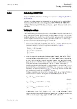
Prepare the IED for verification of settings as outlined in
.
Values of the logical signals for GENPDIF are available on the local HMI under
Main
menu/Tests/Function status/Differential/GENPDIF(87G,IdG)/GENPDIF:1
.
The Signal Monitoring in PCM600 shows the same signals that are available on the
local HMI.
6.3.4.1
Verifying the settings
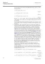
1.
Go to
Main menu/Test/Function test modes/Differential protection
and
make sure all other functions, configured to the same current transformer inputs
as the generator differential protection, are set off. Make sure that the generator
differential function is unblocked.
2.
Connect the test set for injection of three-phase current to the current IEDs,
which are connected to the CTs on the HV side of the generator.
3.
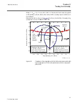
Increase the current in phase L1 until the protection function operates and note
the operating current.
1MRK 502 049-UEN A
Section 6
Testing functionality
47
Commissioning manual
Содержание REG650 ANSI
Страница 1: ...Relion 650 series Generator protection REG650 Commissioning manual...
Страница 2: ......
Страница 8: ......
Страница 20: ...12...
Страница 40: ...32...
Страница 42: ...34...
Страница 50: ...42...
Страница 120: ...112...
Страница 126: ...118...
Страница 142: ...134...
Страница 143: ...135...

