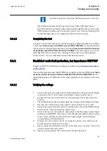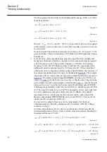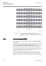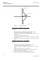
The three symmetrical currents of the fundamental frequency, 50 Hz (or 60 Hz),
must be as follows:
i
I
t
L
1
2
2
50 0
2
=
⋅ ⋅
⋅ ⋅
⋅ −
(
)
sin
.
/
π
π
IECEQUATION2325 V1 EN
(Equation 5)
i
I
t
L
2
2
2
50 0
2
2
3
=
⋅ ⋅
⋅ ⋅
⋅ −
− ⋅
(
)
sin
.
/
/
π
π
π
IECEQUATION2326 V1 EN
(Equation 6)
i
I
t
L
3
2
2
50 0
2
4
3
=
⋅ ⋅
⋅ ⋅
⋅ −
− ⋅
(
)
sin
.
/
/
π
π
π
IECEQUATION2327 V1 EN
(Equation 7)
Where I = U
gen
/ √(3) /
ForwardX
= 14107 A. The actual CT ratio must be applied
to this primary current so that correct value of the secondary injected current can
be calculated.
Expected result: The function must measure a reactance X =
ForwardX
= 59.33
percent of Zbase, which corresponds to 0.565 Ohm. The TRIP signal must remain
FALSE (0).
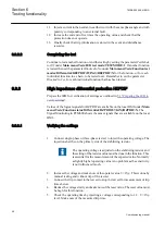
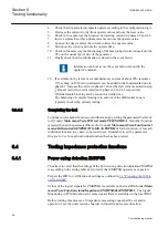
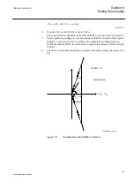
3. In the last step of the commissioning procedure, apart from the fundamental
frequency current described above, another current component must be injected,
with a frequency equal to the nominal frequency ± 1.000 Hz. For nominal
frequency 50 Hz, first 49.000 Hz and then 51.000 Hz. The magnitude of this
additional current component must be 0.9 times current I. If the symmetrical
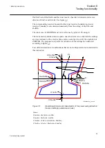
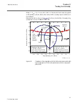
additional current component in all three phases has 49.000 Hz, the trajectory of
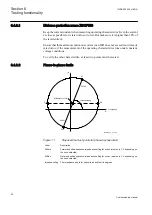
the complex impedance has to be exactly as illustrated in
. The complex
impedance Z(R, X) travels from the right side towards the left side, as shown in
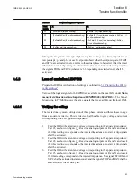
. The Boolean output signal GENMODE must be set to TRUE (1) as
shown in
. If the X-line is set in a way, so that the zone 2 begins on the
power transformer HV-side terminals, as described in
, then all the pole
slips occur in zone 2, and this can be observed as the Boolean output TRIPZ2,
which must be periodically (with 1 Hz) set to TRUE (1), and then reset to FALSE
(0). The output trip must be set to TRUE (1) and persist at that value under this
test. If the additional component of the current is 51.000 Hz, the complex
impedance Z(R, X) travels from the left side towards the right side and the
Boolean output signal MOTMODE has to be set to TRUE (1). The rest of the
signals must be as under the 49 Hz test.
If a test set (for example, Omicron) is to be programmed for the above
commissioning test, then the currents must be as follows (while the voltages
remain as in step 2):
Currents (instantaneous values) with two components, of which one has the
fundamental frequency, that is, 50 Hz or 60 Hz, must be as follows. Example for
fundamental frequency 50 Hz:
i
I
t
I
t
L
1
2
2
50 0
2
2 0 9
2
49 0
2
=
⋅
⋅
⋅ −
(
)
+
⋅
⋅ ⋅
⋅
⋅ −
(
)
sin
.
/
.
sin
.
/
π
π
π
π
IECEQUATION2322 V1 EN
(Equation 8)
i
I
t
I
t
L
2
2
2
50 0
2
2
3
2 0 9
2
49 0
2
=
⋅ ⋅
⋅
⋅ −
− ⋅
(
)
+
⋅
⋅ ⋅
⋅
⋅ −
−
sin
.
/
/
.
sin
.
/
π
π
π
π
π
2
2
3
⋅
(
)
π
/
IECEQUATION2323 V1 EN
(Equation 9)
i
I
t
I
t
L
3
2
2
50 0
2
4
3
2 0 9
2
49 0
2
=
⋅ ⋅
⋅
⋅ −
− ⋅
(
)
+
⋅
⋅ ⋅
⋅
⋅ −
−
sin
.
/
/
.
sin
.
/
π
π
π
π
π
4
4
3
⋅
(
)
π
/
IECEQUATION2324 V1 EN
(Equation 10)
Section 6
1MRK 502 049-UEN A
Testing functionality
56
Commissioning manual
Содержание REG650 ANSI
Страница 1: ...Relion 650 series Generator protection REG650 Commissioning manual...
Страница 2: ......
Страница 8: ......
Страница 20: ...12...
Страница 40: ...32...
Страница 42: ...34...
Страница 50: ...42...
Страница 120: ...112...
Страница 126: ...118...
Страница 142: ...134...
Страница 143: ...135...


