background image

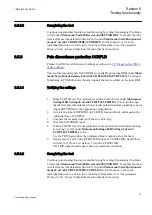
6.5.5.4 

Verifying the re-trip mode

Choose the mode below, which corresponds to the actual case.

In the cases below it is assumed that 

FunctionMode

 = 

Current

 as set under 

Main

menu/Settings/IED Settings/Current/CCRBRF(50BF)/CCRBRF:1

.

Checking the case without re-trip, 

RetripMode = Retrip Off

1.

Set 

RetripMode

 = 

Retrip Off

.

2.

Apply the fault condition, including start of CCRBRF, well above the set current
value.

3.

Verify that no re-trip, but back-up trip is achieved after set time.

4.

Disconnect AC and START input signals.

Checking the re-trip with current check, 

RetripMode = CB Pos Check

1.

Set 

RetripMode

 = 

CB Pos Check

.

2.

Apply the fault condition, including start of CCRBRF, well above the set current
value.

3.

Verify that re-trip is achieved after set time 

t1

 and back-up trip after time 

t2

4.

Apply the fault condition, including start of CCRBRF, with current below set
current value.

5.

Verify that no re-trip, and no back-up trip is obtained.

6.

Disconnect AC and START input signals.

Checking re-trip without current check, 

RetripMode = No CBPos Check

1.

Set 

RetripMode

 = 

No CBPos Check

.

2.

Apply the fault condition, including start of CCRBRF, without any current.

3.

Verify that re-trip is achieved after set time 

t1

, and back-up trip after time 

t2

.

4.

Apply the fault condition, including start of CCRBRF, with current below set
current value.

5.

Verify that re-trip is achieved after set time 

t1

, but no back-up trip is obtained.

6.

Disconnect AC and START input signals.

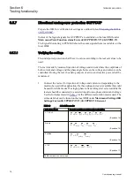
6.5.5.5 

Verifying the back-up trip mode

In the cases below it is assumed that 

FunctionMode

 = 

Current

 is selected.

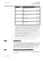
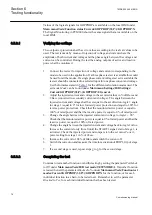
Checking that back-up tripping is not achieved at normal CB tripping

Use the actual tripping modes. The case below applies to re-trip with current check.

Section 6

1MRK 502 049-UEN A

Testing functionality

70

Commissioning manual

Содержание REG650 ANSI

Страница 1: ...Relion 650 series Generator protection REG650 Commissioning manual...

Страница 2: ......

Страница 3: ...Document ID 1MRK 502 049 UEN Issued October 2016 Revision A Product version 1 3 Copyright 2013 ABB All rights reserved...

Страница 4: ...L Project for use in the OpenSSL Toolkit http www openssl org This product includes cryptographic software written developed by Eric Young eay cryptsoft com and Tim Hudson tjh cryptsoft com Trademarks...

Страница 5: ...rning electrical equipment for use within specified voltage limits Low voltage directive 2006 95 EC This conformity is the result of tests conducted by ABB in accordance with the product standards EN...

Страница 6: ...roduct failure would create a risk for harm to property or persons including but not limited to personal injuries or death shall be the sole responsibility of the person or entity applying the equipme...

Страница 7: ...lectrician is allowed to carry out the electrical installation National and local electrical safety regulations must always be followed The frame of the IED has to be carefully earthed Whenever change...

Страница 8: ......

Страница 9: ...ance testing 21 Commissioning checklist 21 Checking the power supply 22 Energizing the IED 22 Checking the IED operation 22 IED start up sequence 22 Setting up communication between PCM600 and the IED...

Страница 10: ...st 45 Restricted earth fault protection low impedance REFPDIF 45 Verifying the settings 45 Completing the test 46 High impedance differential protection HZPDIF 46 Verifying the settings 46 Completing...

Страница 11: ...ants TRPTTR 67 Checking operate and reset values 67 Completing the test 68 Breaker failure protection phase segregated activation and output CCRBRF 68 Checking the phase current operate value IP 69 Ch...

Страница 12: ...settings 85 Completing the test 85 100 Stator earth fault protection 3rd harmonic based STEFPHIZ 86 Testing 86 Verifying settings 87 Completing the test 88 Testing frequency protection functions 89 U...

Страница 13: ...Completing the test 109 Testing metering functions 109 Pulse counter PCGGIO 109 Testing station communication 109 Establishing connection and verifying the IEC 61850 communication 109 Overview 109 Set...

Страница 14: ...tion messages 121 Internal faults 121 Warnings 121 Additional indications 122 Correction procedures 122 Changing and setting the password 122 Identifying IED application problems 122 Inspecting the wi...

Страница 15: ...not in service The chapters are organized in the chronological order in which the IED should be commissioned The relevant procedures may be followed also during the service and maintenance activities...

Страница 16: ...protection and control functions LHMI functions as well as communication engineering for IEC 60870 5 103 IEC 61850 and DNP 3 0 The installation manual contains instructions on how to install the IED...

Страница 17: ...ters and technical data sorted per function The manual can be used as a technical reference during the engineering phase installation and commissioning phase and during normal service The communicatio...

Страница 18: ...he presence of a hazard which could result in electrical shock The warning icon indicates the presence of a hazard which could result in personal injury The caution icon indicates important informatio...

Страница 19: ...t Main menu Settings LHMI messages are shown in Courier font For example to save the changes in non volatile memory select Yes and press Parameter names are shown in italics For example the function c...

Страница 20: ...12...

Страница 21: ...al protection three winding 0 1 1 REFPDIF 87N Restricted earth fault protection low impedance 0 1 HZPDIF 87 1Ph High impedance differential protection 0 1 1 1 GENPDIF 87G Generator differential protec...

Страница 22: ...underpower protection 0 1 1 1 GOPPDOP 32 Directional overpower protection 0 2 2 2 AEGGAPC 50AE Accidental energizing protection for synchronous generator 1 1 1 NS2PTOC 46I2 Negative sequence time ove...

Страница 23: ...I103POSCMD IED commands with position and select for IEC60870 5 103 50 50 50 Apparatus control and Interlocking APC8 Apparatus control for single bay max 8 app 1CB incl interlocking 0 1 SCILO 3 Logica...

Страница 24: ...40 AND Configurable logic blocks 280 280 280 SRMEMORY Configurable logic blocks 40 40 40 RSMEMORY Configurable logic blocks 40 40 40 Q T Configurable logic blocks Q T 0 1 ANDQT Configurable logic bloc...

Страница 25: ...es presentation of secondary analog inputs 600TRM 1 1 1 AM_S_P4 Function block for service values presentation of secondary analog inputs 600AIM 1 1 1 CNTGGIO Event counter 5 5 5 L4UFCNT Event counter...

Страница 26: ...0 communication general protocol 1 1 1 RS485DNP DNP3 0 for RS 485 communication protocol 1 1 1 CH1TCP DNP3 0 for TCP IP communication protocol 1 1 1 CH2TCP DNP3 0 for TCP IP communication protocol 1 1...

Страница 27: ...ion component 1 1 1 GOOSEDPRCV GOOSE function block to receive a double point value 32 32 32 GOOSEINTRCV GOOSE function block to receive an integer value 32 32 32 GOOSEMVRCV GOOSE function block to re...

Страница 28: ...6 ATHSTAT Authority status 1 ATHCHCK Authority check 1 AUTHMAN Authority management 1 FTPACCS FTPS access with password 1 DOSFRNT Denial of service frame rate control for front port 1 DOSLAN1 Denial...

Страница 29: ...d configuration Site acceptance testing SAT or commissioning testing is typically done to verify that the installed IED is correctly set and connected to the power system SAT requires that the accepta...

Страница 30: ...to energizing a single IED Set the IED time if no time synchronization source is configured Check the self supervision function in Main menu Diagnostics Internal events or Main menu Diagnostics IED s...

Страница 31: ...the PC or workstation to the LAN WAN network 4 Configure the IED IP addresses in the PCM600 project for each IED to match the IP addresses of the physical IEDs Setting up IP addresses The IP address...

Страница 32: ...atically detect that Tx signals from the IED are received on the Tx pin on the PC Thus a straight standard Ethernet cable can be used When a PC is connected to the IED and the setting DHCPServer is se...

Страница 33: ...1 en vsd IEC13000057 V1 EN Figure 3 Select Search programs and files 2 Type View network connections and click on the View network connections icon 1MRK 502 049 UEN A Section 3 Starting up 25 Commissi...

Страница 34: ...elect Properties IEC13000059 1 en vsd IEC13000059 V1 EN Figure 5 Right click Local Area Connection and select Properties 4 Select the TCP IPv4 protocol from the list of configured components using thi...

Страница 35: ...r DHCPServer is set to On in the IED IEC13000061 1 en vsd IEC13000061 V1 EN Figure 7 Select Obtain an IP address automatically 6 Select Use the following IP address and define IP address and Subnet ma...

Страница 36: ...for this set up to work 3 6 Writing an application configuration to the IED Ensure that the IED includes the correct application configuration according to project specifications The application confi...

Страница 37: ...dary loop resistance measurement to confirm that the current transformer secondary loop DC resistance is within specification and that there are no high resistance joints in the CT winding or wiring E...

Страница 38: ...test plug handle When the test plug handle is inserted it first blocks the trip and alarm circuits then it short circuits the CT secondary circuit and opens the VT secondary circuits making the IED av...

Страница 39: ...arity are in accordance with the IED specifications 3 10 2 Binary output circuits Preferably disconnect the binary output connector from the binary output cards Check all connected signals so that bot...

Страница 40: ...32...

Страница 41: ...Configuration Communication Station communication IEC61850 8 1 1 must be set to Front To enable GOOSE communication via rear port the parameter PortSelGOOSE must be set to LAN1 To enable MMS communica...

Страница 42: ...34...

Страница 43: ...he work more efficient For example the tool may be configured to only show time tagged events and to exclude analog information and so on Check the disturbance report settings to ensure that the indic...

Страница 44: ...l manual Three phase test equipment Content of the technical manual Application and functionality summaries Function blocks Logic diagrams Input and output signals A list of setting parameters Technic...

Страница 45: ...XH8 RTXH18 or RTXH24 are a part of the COMBITEST system which provides secure and convenient testing of the IED When using the COMBITEST preparations for testing are automatically carried out in the p...

Страница 46: ...ect the current and voltage terminals Pay attention to the current polarity Make sure that the connection of input and output current terminals and the connection of the residual current conductor is...

Страница 47: ...e function to be tested Event function blocks can also be individually blocked to ensure that no events are reported to a remote station during the test This is done by setting the parameter EvDisable...

Страница 48: ...ion Analog modules Measured values such as current and voltages as well as active reactive and apparent power power factor phase angles as well as positive and negative and zero sequence currents and...

Страница 49: ...s Verify alarm and blocking signals Use the disturbance handling tool in PCM600 to evaluate that the protection function has received the correct data and responded correctly signaling and timing Use...

Страница 50: ...42...

Страница 51: ...1 6 1 2 Disturbance report settings When the IED is in test mode the disturbance report can be made active or inactive If the disturbance recorder is turned on during test mode recordings will be made...

Страница 52: ...n function operates and note the operating current 4 Check that the trip and alarm contacts operate according to the configuration logic 5 Decrease the current slowly from operate value and note the r...

Страница 53: ...ial REFPDIF 87 INd REFPDIF X The Signal Monitoring in PCM600 shows the same signals that are available on the local HMI 6 3 2 1 Verifying the settings 1 Connect the test set for single phase current i...

Страница 54: ...PDIF are available on the local HMI under Main menu Tests Function status Differential HZPDIF 87 IdN HZPDIF X The Signal Monitoring in PCM600 shows the same signals that are available on the local HMI...

Страница 55: ...nder Main menu Tests Function test modes Differential HZPDIF 87 IdN HZPDIF Xfor the function or for each individual function in a chain to be tested next Remember to set the parameter Blocked to Yes f...

Страница 56: ...ypically checked by primary testing 6 3 4 2 Completing the test Continue to test another function or end the testing by setting the parameter TestMode to Off under Main menu Tests IED test mode TESTMO...

Страница 57: ...nd a second part to verify the operation of ZMRPSB The proposed test points for validation of the settings are numbered according to figure 10 Test of the interactions or combinations that are not con...

Страница 58: ...4 according to figure 10 6 4 1 2 Testing the power swing detection function ZMRPSB Preconditions The following output signals shall be configured to binary outputs ZOUT measured impedance within outer...

Страница 59: ...hen the fault shall be applied 2 Start the test sequence by continuously reducing the voltage and observe that the output signal ZOUT may come but not START If the input I0CHECK is configured connecte...

Страница 60: ...mho characteristic at least two points must be tested 6 4 2 2 Phase to phase faults jX R Ohm phase ImpedanceAng ZxFwd ZxRev P1 P2 P3 P4 Midpoint of circle IEC09000173_2_en vsd IEC09000173 V2 EN Figur...

Страница 61: ...g in PCM600 shows the same signals that are available on the local HMI 6 4 3 1 Verifying the settings The test is done by means of injection of three phase current and three phase voltage from a moder...

Страница 62: ...corresponding to Test 4 and measure the time to activation of signal TRZ1 This time shall be compared to tZ1 IEC06000513 2 en vsd R X Underexcitation Protection Restrain area Z1 Fast zone Z2 Slow zon...

Страница 63: ...y phase voltages must be fed to IED with magnitudes proportional to Ugen 3 that is taking into the account the actual PT ratio in the IED If three symmetrical fundamental frequency currents proportion...

Страница 64: ...hown in Figure 13 The Boolean output signal GENMODE must be set to TRUE 1 as shown in Figure 14 If the X line is set in a way so that the zone 2 begins on the power transformer HV side terminals as de...

Страница 65: ...s Imaginary part X of Z in Ohms trajectory Z R X R Trajectory of the Z R X for I I 50Hz I 49Hz I 50Hz determines point A I 49Hz makes Z R X rotate SE Zone 1 Trajectory of the Z R X for I I 50Hz I 51Hz...

Страница 66: ...r LEPDIS are available on the local HMI under Main menu Tests Function status Impedance LEPDIS LEPDIS 1 The Signal Monitoring in PCM600 shows the same signals that are available on the local HMI Load...

Страница 67: ...on test modes Impedance LEPDIS LEPDIS 1 for the function or for each individual function in a chain to be tested next Remember to set the parameter Blocked to Yes for each individual function that has...

Страница 68: ...repeat the test injecting current into phases L2 L3 and L3 L1 with the appropriate phase angle of injected currents 8 Block higher set stages when testing lower set stages by following the procedure...

Страница 69: ...n is selected set the injection current to lag the polarizing voltage by an angle equal to RCA 180 3 Increase the injected current and note the value at which the studied step of the function operates...

Страница 70: ...ailable on the local HMI under Main menu Tests Function status Current SDEPSDE 67N IN SDEPSDE 1 The Signal Monitoring in PCM600 shows the same signals that are available on the local HMI 6 5 3 1 Measu...

Страница 71: ...UNREL is activated which is visible in the Application Configuration in PCM600 when the IED is in online mode Compare the voltage with the set value UNRel 8 Continue to test another function or comple...

Страница 72: ...setting for the set directional element Note that for operation both the injected current and voltage must be greater than the set values INRel and UNRel respectively The function activates the START...

Страница 73: ...hat for operation both the injected current and voltage must be greater than the set values INRel and UNRel respectively The function activates the START and STDIRIN output 3 Measure with angles j aro...

Страница 74: ...lected 4 Continue to test another function or complete the test by setting the test mode to Off Residual overvoltage release and protection Procedure 1 Measure that the operate voltage is equal to the...

Страница 75: ...t terminals of the IED 2 Set the Time constant 1 Tau1 and Time Constant 2 Tau2 temporarily to 1 minute 3 Set the three phase injection currents slightly lower than the set operate value of stage IBase...

Страница 76: ...f another function is tested then set the parameter Blocked to No under Main menu Tests Function test modes Current TRPTTR 49 T TRPTTR X for the function or for each individual function in a chain to...

Страница 77: ...as set under Main menu Settings IED Settings Current CCRBRF 50BF CCRBRF 1 1 Apply the fault condition including START of CCRBRF with a current just below set IN Pickup_N 2 Repeat the fault condition...

Страница 78: ...fault condition including start of CCRBRF with current below set current value 5 Verify that no re trip and no back up trip is obtained 6 Disconnect AC and START input signals Checking re trip without...

Страница 79: ...after set time If selected re trip should also appear 4 Disconnect AC and START input signals Checking the case BuTripMode 2 out of 4 The earth fault current setting IN may be equal to or below phase...

Страница 80: ...Checking the case with fault current below set value I BlkCont The case shall simulate a case where the fault current is very low and operation will depend on CB position signal from CB auxiliary cont...

Страница 81: ...rdance when external pole discordance signaling is used input EXTPDIND in the application configuration 2 Activate the input EXTPDIND on CCRPLD function block and measure the operating time of CCRPLD...

Страница 82: ...e test set for injection of voltage and current corresponding to the mode to be used in the application If a three phase test set is available this could be used for all the modes If a single phase cu...

Страница 83: ...d power and that the reactive power is equal to 100 of rated power 4 Change the angle between the injected current and voltage back to 0 Decrease the current slowly until the START1 signal start of st...

Страница 84: ...l be set equal to the set direction Angle1 angle for stage 1 equal to 0 for low forward power protection and equal to 180 for reverse power protection Check that the monitored active power is equal to...

Страница 85: ...k the time delay 7 Check that all trip and start contacts operate according to the configuration signal matrises 8 Finally check that start and trip information is stored in the event menu 9 Inject ra...

Страница 86: ...p 1 of the function operates Start signal ST1 must be activated when amplitude of the negative sequence current lies slightly above the start level I2 1 Corresponding trip signals TR1 and TRIP is acti...

Страница 87: ...ocal HMI under Main menu Tests Function status Current VRPVOC 51V I U VRPVOC 1 The Signal Monitoring in PCM600 shows the same signals that are available on the local HMI 6 5 11 1 Verifying the setting...

Страница 88: ...et and the influence on the operate value has to be calculated when testing the operate value is completed 5 Operate time measurement Definite times may be tested as above For inverse time characteris...

Страница 89: ...olts is calculated according to the following equations For phase to ground measurement U UBase VT VTprim 1 100 3 sec IECEQUATION2430 V1 EN Equation 23 For phase to phase measurement U UBase VT VTprim...

Страница 90: ...n menu Tests Function test modes Voltage UV2PTUV 27 2U UV2PTUV 1 for the function or for each individual function in a chain to be tested next Remember to set the parameter Blocked to Yes for each ind...

Страница 91: ...d voltage U1 Set start voltage for step 1 For example if the measured voltage jumps from 0 to 1 2 times the set start voltage level and time multiplier k1 is set to 0 05 s default value then the TR1 a...

Страница 92: ...d note the reset value 5 Set and apply about 20 higher voltage than the measured operate value for one phase 6 Measure the time delay for the TR1 signal and compare it with the set value 7 Check the i...

Страница 93: ...cy for the injection voltage and increasing the injection voltage to get the desired overexcitation level 3 Connect the alarm contact to the timer and set the time delay tAlarm temporarily to zero 4 I...

Страница 94: ...nection to the IED The test set shall be capable to generate third harmonic voltages One voltage UN3 is connected to the residual voltage input related to the terminal side of the generator The second...

Страница 95: ...overvoltage function 95 stator earth fault protection This part of the protection can be tested separately by means of fundamental frequency voltage injection from a test equipment 6 6 5 2 Verifying s...

Страница 96: ...et the parameter Blocked to Yes for each individual function that has been tested Generator rotor winding and its associated dc supply electric circuit is typically fully insulated from the earth Ther...

Страница 97: ...ly decrease the voltage frequency by steps of 40 mHz until the START signal appears during each step apply the voltage signal for a time that is either at least 10 longer than tDelay 100 ms or a suita...

Страница 98: ...s a set value of the SMAI UBase is the value in the GBASVAL group identified by the setting GlobalBaseSel 5 Slowly decrease the frequency of the applied voltage to a value below StartFrequency as expl...

Страница 99: ...e frequency by steps of 40 mHz until the START signal appears during each step apply the voltage signal for a time that is either at least 10 longer than tDelay 100 ms or a suitable time to monitor th...

Страница 100: ...s a set value of the SMAI UBase is the value in the GBASVAL group identified by the setting GlobalBaseSel 5 Slowly increase the frequency of the applied voltage to a value above StartFrequency as expl...

Страница 101: ...ue and compare it with the set value 5 Increase the frequency to rated operating conditions and zero rate of change 6 Check that the START signal resets 7 Instantaneously decrease the frequency of the...

Страница 102: ...ISCPOS binary input The signal BLKU should appear with almost no time delay No signals BLKZ and 3PH should appear on the IED Only the distance protection function can operate Undervoltage dependent fu...

Страница 103: ...2 UL1 a 2 UL2 a UL3 EQUATION707 V1 EN Equation 37 Where UL1 UL2 and UL3 IEC00000275 V1 EN the measured phase voltages 2 3 3 1 0 5 2 j a e j p IECEQUATION00022 V1 EN 4 Compare the result with the set v...

Страница 104: ...43 Where UL1 UL2 and UL3 IEC00000275 V1 EN the measured phase voltages 4 Compare the result with the set value consider that the set value 3U0 is in percentage of the base voltage of the zero sequenc...

Страница 105: ...nnect the nominal voltages in all three phases and feed a current below the operate level in all three phases 7 Keep the current constant Disconnect the voltage in all three phases simultaneously The...

Страница 106: ...n the local HMI At commissioning and periodical checks the functions shall be tested with the used settings To test a specific function it might be necessary to change some setting parameters for exam...

Страница 107: ...t connection for a 1 breaker diameter with one phase voltage connected to the line side Test equipment UMeasure Ph N Ph Ph en08000027 vsd U Bus U Line N IED U Bus N UL1 UL2 UL3 N Input Phase L1 L2 L3...

Страница 108: ...D Testing the frequency difference The frequency difference is in the example set at 0 20 Hz on the local HMI and the test should verify that operation is achieved when the FreqDiffMax frequency diffe...

Страница 109: ...1 SESRSYN 2 SESRSYN 3 functions These three SESRSYN functions can either be in one two or three different IEDs Table 4 describes the scenario when SESRSYN 1 SESRSYN 2 and SESRSYN 3 all are in the sam...

Страница 110: ...ine 1 Line 2 LN1QB9 LN2QB9 IEC11000274 2 en vsd IEC11000274 V2 EN Figure 21 Objects used in the voltage selection logic Testing the voltage difference Set the voltage difference to 0 15 p u on the loc...

Страница 111: ...Apply voltages U Line for example 100 GblBaseSelLine and U Bus 100 GblBaseSelBus with a phase difference equal to 0 degrees and a frequency difference lower than FreqDiffA and FreqDiffM 2 Check that...

Страница 112: ...ed with different frequency values to verify that the function operates for values lower than the set ones If a modern test set is used the frequency can be changed continuously Testing the reference...

Страница 113: ...of 30 GblBaseSelBus to the U Bus and a single phase voltage of 100 GblBaseSelLine to the U Line 3 Check that the AUTOENOK and MANENOK outputs are activated after set tAutoEnerg respectively tManEnerg...

Страница 114: ...rify that deactivation prevents operation and gives an alarm 1 Connect the signals above to binary inputs and binary outputs 2 Connect the voltage inputs to the analog inputs used for each bus or line...

Страница 115: ...erations to align the statuses 6 10 Testing logic functions 6 10 1 Tripping logic common 3 phase output SMPPTRC Prepare the IED for verification of settings as outlined in 5 1 Preparing the IED to ver...

Страница 116: ...ripLockout Off and the automatic lockout function set AutoLock Off if not used 6 10 1 3 Completing the test Continue to test another function or end the testing by setting the parameter TestMode to Of...

Страница 117: ...tion PCGGIO requires the Parameter Setting tool in PCM600 or an appropriate connection to the local HMI with the necessary functionality A known number of pulses with different frequencies are connect...

Страница 118: ...for the corresponding GOOSE function blocks GOOSEBINRCV and GOOSEINTLKRCV must be set to On in the application configuration To enable GOOSE communication via the front port the parameter GOOSE in Ma...

Страница 119: ...nication Ensure that the IED receives IEC 61850 8 1 data on both ports A and B In the local HMI navigate to Main menu Tests Function status Communication PRP Status LAN1 A LAN1 B and check that both s...

Страница 120: ...112...

Страница 121: ...s should be checked and the symmetry verified Directional functions have information about the measured direction and for example measured impedance These values must be checked and verified as correc...

Страница 122: ...le can be used to polish the contacts Emery cloth or similar products must not be used as insulating grains of abrasive may be deposited on the contact surfaces and cause failure Make sure that all IE...

Страница 123: ...condary injection The periodic maintenance test is done by secondary injection from a portable test set Each protection shall be tested according to the secondary injection test information for the sp...

Страница 124: ...tighten the terminal carefully Measurement of service currents After a maintenance test it is recommended to measure the service currents and service voltages recorded by the protection IED The servi...

Страница 125: ...open terminal with a removed fuse or open miniature circuit breaker with an open connection wrong setting and so on Thus a list should be prepared of all items disturbed during test so that all can be...

Страница 126: ...118...

Страница 127: ...xternal test device If the problem remains contact ABB for repair or replacement actions 8 1 2 Identifying runtime errors 1 Check the error origin from IED s internal event list Main menu Diagnostics...

Страница 128: ...n menu Tests Function status Communication DOSLAN1 1 Outputs The X1 communication port on the rear side of the IED is for optical Ethernet via LC connector Check that the LINKUP value is 1 that is the...

Страница 129: ...al Fault Real Time Clock Error Hardware error with the real time clock Internal Fault Runtime Exec Error One or more of the application threads are not working properly Internal Fault SW Watchdog Erro...

Страница 130: ...gnal status data is found under the IED status and in the internal event list Table 7 Additional indications Warning indication Additional information Time Synch Error Source of the time synchronizati...

Страница 131: ...ed without special skills In PCM600 change the parameter CTStarPointn n the number on the current input under the parameter settings for each current input Check the actual state of the connected bina...

Страница 132: ...1 4711 A71D BBC76B60BA3D V1 EN Figure 23 Testing output contacts using the voltage drop method 1 Contact current 2 Contact voltage drop 3 Load 4 Supply voltage Section 8 1MRK 502 049 UEN A Troubleshoo...

Страница 133: ...mode select Main menu Tests IED test mode TESTMODE 1 and set the parameter to On 2 To operate or force the output relay to operate select and then navigate to the board with the actual binary output...

Страница 134: ...or operated on the LHMI Set the parameter TestMode to Off after completing these tests The Start LED stops flashing when the relay is no longer in test mode An initially high contact resistance does n...

Страница 135: ...ker failure protection BI Binary input BOS Binary outputs status BR External bistable relay BS British Standards CB Circuit breaker CCITT Consultative Committee for International Telegraph and Telepho...

Страница 136: ...Protocol DI Digital input DLLB Dead line live bus DNP Distributed Network Protocol as per IEEE Std 1815 2012 DR Disturbance recorder DRAM Dynamic random access memory DRH Disturbance report handler DT...

Страница 137: ...connector type Plastic fiber connector HMI Human machine interface HSAR High speed autoreclosing HV High voltage HVDC High voltage direct current IDBS Integrating deadband supervision IEC Internationa...

Страница 138: ...the TCP IP protocol suite widely used on Ethernet networks IP is a connectionless best effort packet switching protocol It provides packet routing fragmentation and reassembly through the data link la...

Страница 139: ...ess level that is in near proximity to the measured and or controlled components PSM Power supply module PST Parameter setting tool within PCM600 PT ratio Potential transformer or voltage transformer...

Страница 140: ...layer protocol used on Ethernet and the Internet TCP IP Transmission control protocol over Internet Protocol The de facto standard Ethernet protocols incorporated into 4 2BSD Unix TCP IP was developed...

Страница 141: ...a whole number of leap seconds to synchronize it with Universal Time 1 UT1 thus allowing for the eccentricity of the Earth s orbit the rotational axis tilt 23 5 degrees but still showing the Earth s i...

Страница 142: ...134...

Страница 143: ...135...

Страница 144: ...ce ABB AB does not accept any responsibility whatsoever for potential errors or possible lack of information in this document We reserve all rights in this document and in the subject matter and illus...

Отзывы: