


54
January 2005
ABB i-bus
®
EIB
ABB Powernet EIB
Control value
Output
Control value
Regulator
internal
0
0
100%
100%
80%
20%
20%
80%
The base setpoint can be modified as
often as necessary via the bus. To do
so, a 2-byte temperature value must
be sent to the object “Base setpoint”.
The setpoint temperature can be
changed manually via the rocker
buttons on the panel display. The
parameters “Area for manual setpoint
setting”, “Maximum increasing of
setpoint at heating” and “Maximum
lowering of control value at cooling”
determine the scope for modifying the
setpoint. If a new telegram is sent to
the communication object “Base
setpoint” after a manual setpoint
adjustment, the manual setpoint
adjustment can also be reversed.
Heating/cooling
To be able to address the various
controller types for heating or cooling
mode, the room thermostat can be
parameterised as a continuous or
switching controller. In the case of a
switching controller, it is possible to
choose between a PWM controller (“PI
controller”) and a “Two-position
controller”.
In the case of a continuous control
response and a switching PWM
controller, the preset control
parameters regarding the installation
type of the heating or air conditioning
system can be used. If other control
parameters are needed, they can be
set individually via the free
parameterisation option. This option
should only be used if the user has
sufficient experience in control
technology.
The continuous controller sends its con-
trol value to a 1-byte object. Electromo-
tive or electrothermal drives which are
connected to heating actuators with
PWM control can thus be controlled.
To prevent unnecessary bus loads, it
is possible to set by how much the
control value must change in order to
be sent on the bus. The setting is
carried out as a percentage. The
sending of the control value is preset
by a cyclic period, provided it has not
been modified. This cycle time should
not be set too low (e.g. every 10 min).
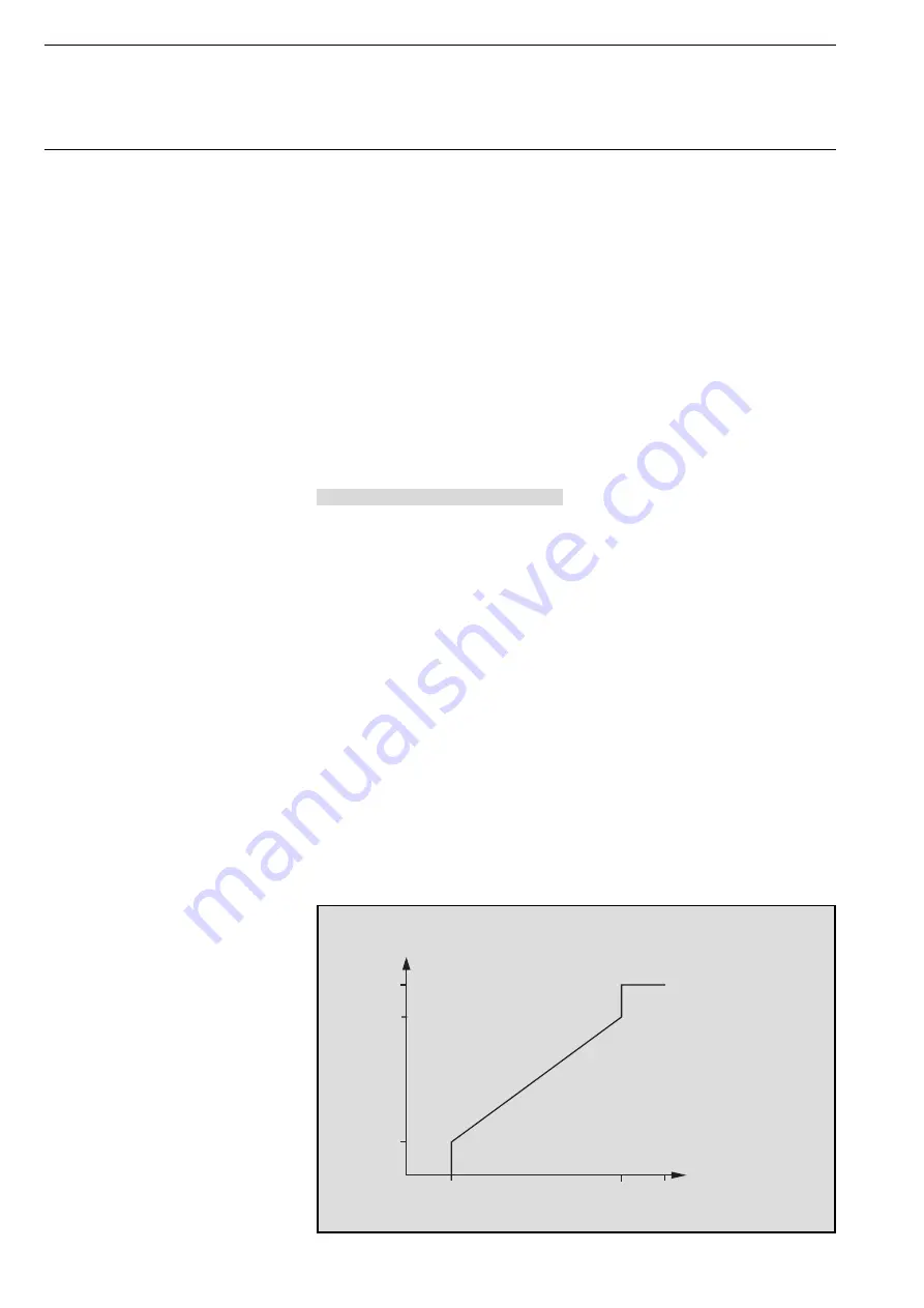
In the case of a switching PWM
controller, the output value of the
controller (0...255) is converted into
an ON/OFF ratio. If e.g. a control value
of 70% should be issued, the ON time
is 7 min and the OFF time is 3 min at
a preset cycle time of 10 min. The
dynamic range can also be limited in
the same way as a continuous
controller. The parameters “PWM
cycle is 0% up to control value” and
“PWM cycle is 100% up to control
value” are used for this purpose. If
e.g. a maximum control value of 80%
is set, the controller automatically
sends the value 255 when a control
value of 204 is exceeded. (See also
the diagram below)
To optimise the control characteristics
of the heating or cooling system, the
“Cycle time of the control value” can
be set. To set the correct cycle time,
the type of heating or cooling as well
as the valve drive used should be
taken into account. The following re-
commendations can be used:
LEANtouch (monochrome),
SMARTtouch (monochrome, colour)
Type: 6x36/30M(-500), 6x36/100x(-500), 6x36/100CB


