


I/O MAP
• I/O MAP, Possibility to assign any digital, system or panel I/O to any arbitrary
physical I/O channel.
- Under the function DIG both board place and channel on the board are defined and
the position is given a logical I/O number between 1 and 190.
• Under SYS the required system-inputs and outputs are defined, by entering board
place and channel number. To continue in the menue, answer the question
CONTINUE with YES.
- Under PANEL are, in the same way, inputs and outputs for remote panel defined.
- Under LINK I/O a physical output is connected to a physical input, so that the
output is activated/resetted when the input is activated/reseted.
- The desired input must be defined as digital, system or panel input before Unking it
to an output.
- To change a link, first clear the linked I/O table and then define all desired links again.
It is possible to link more than one output to the same input. Up to 15 links are
allowed.
NOTE! If I/O MAP is used, all digital inputs and outputs must be defined on defined digital
boards in the system. It is adviseable to note on paper all mapped and linked I/O,
see 5.2.4.7.3 for a list of available system and panel I/O.The following are connection
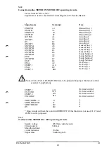
tables for digital I/O boards with the recommended placing in the controlcabinet:
CONNECCTTON TABLE
digital I/O board place User contact User contact relay
place 1AP11 XS11 or XT 11 AP21.XT1
place 2 AP12 XS12 or XT 12 AP22.XT1
place 3 AP13 XS13 or XT 13 AP23.XT1
place 4 AP14 XS14 or XT 14 AP24.XT1
place 5 AP15 XS15 or XT 15 AP25.XT1
place 6 AP16 XS16 or XT 16 AP26.XT1
INSTALLATION S3
3:23
Содержание IRB 2000
Страница 2: ...Product Manual IRB 2000 3HAB 0007 2 January 1993 M93 ABB Robotics Products Jk It It ASEA BROWN BOVERI ...
Страница 8: ...Description 1KB 2000 ...
Страница 10: ...Description 1KB 2000 ...
Страница 12: ...Description 1KB 2000 6 ...
Страница 20: ...Description 1KB 2000 14 ...
Страница 32: ...Description 1KB 2000 26 ...
Страница 40: ...5 3 2 Dimensional drawings Description 34 1KB 2000 ...
Страница 41: ..._200 _D D_ Description 35 1KB 2000 ...
Страница 44: ...Description 1KB 2000 38 ...
Страница 64: ...Description 1KB 2000 58 ...
Страница 77: ...Safety 1KB 2000 IBB 3000 12 1KB 3200 1KB 6000 ...
Страница 78: ...Installation IRB 2000 3HAB 0003 2 January 1993 M93 0 1 JIM ABB Robotics Products ASEA BROWN BOVERI ...
Страница 80: ...Installation H B 2000 ...
Страница 82: ...Installation 1KB 2000 ...
Страница 91: ...Installation 1KB 2000 12 ...
Страница 95: ...Installation 1KB 2000 16 ...
Страница 105: ...3HAB 0003 8 January 1993 M93 INSTALLATION Robot control system S3 Ml It It ABB Robotics Products ASEA BROWN BOVERI ...
Страница 110: ...INSTALLATION S3 0 4 ...
Страница 111: ...1 SAFETY INSTRUCTIONS AND RECOMMENDATIONS See separate document in the Product manual INSTALLATION S3 1 1 ...
Страница 112: ...INSTALLATION S3 1 2 ...
Страница 160: ...INSTALLATION 3 46 ...
Страница 234: ...INSTALLATION 5 70 ...
Страница 262: ...INSTALLATION S3 7 6 ...


