L2234
Emax
149/158
Doc. No.
Model
1SDH000460R0002
Apparatus
Scale
Page No.
L2778
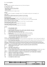
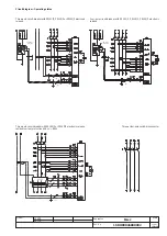
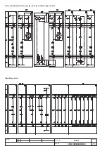
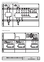
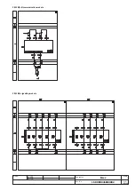
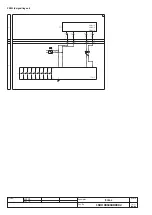
18. Circuit diagrams
Warning
Before installing the circuit-breaker, carefully read notes F and O on the circuit diagrams.
Operating status shown
The circuit diagram is for the following conditions:
- withdrawable circuit-breaker, open and racked-in
- circuits de-energised
- releases not tripped
- motor operating mechanism with springs unloaded.
Versions
The diagram shows a circuit-breaker in withdrawable version; it can be applied to a fixed version circuit-breaker as well.
Fixed version
The control circuits are fitted between terminals XV (connector X is not supplied).
With this version, the applications indicated in figures 31 and 32 cannot be provided.
Withdrawable version
The control circuits are fitted between the poles of connector X (terminal box XV is not supplied).
Version without overcurrent release
With this version, the applications indicated in figures 13, 14, 41, 42, 43, 44, 45, 46, 47, 48, 62 cannot be provided.
Version with PR121/P electronic release
With this version, the applications indicated in figures 42, 43, 44, 45, 46, 47, 48 cannot be provided.
Version with PR122/P electronic release
With this version, the applications indicated in figure 41 cannot be provided.
Version with PR123/P electronic release
With this version, the applications indicated in figure 41 cannot be provided.
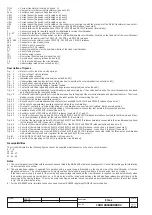
Caption
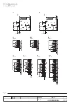
= Circuit diagram figure number
*
= See note indicated by the letter
A1
= Circuit-breaker accessories
A3
= Accessories applied to the fixed part of the circuit-breaker (for withdrawable version only)
A4
= Example switchgear and connections for control and signalling, outside the circuit-breaker
A13
= PR021/K signalling unit (outside the circuit-breaker)
AY
= SACE SOR TEST UNIT Test/monitoring Unit (see note R)
D
= Electronic time-delay device of the undervoltage release, outside the circuit-breaker
F1
= Delayed-trip fuse
K51
= PR121/P, PR122/P, PR123/P electronic release with the following protection functions:
- L overload protection with inverse long time-delay trip-setting I1
- S short-circuit protection with inverse or definite short time-delay trip-setting l2
- I short-circuit protection with instantaneous time-delay trip-setting l3
- G earth fault protection with inverse short time-delay trip-setting l4
K51/1...8
= Contacts for the PR021/K signalling unit
K51/GZin(DBin)= Zone selectivity: for protection G (only with Vaux and PR122/P or PR123/P release) or "reverse" direction input for protection D
(only with Vaux and PR123/P release)
K51/GZout(DBout) = Zone selectivity: for protection G (only with Vaux and PR122/P or PR123/P release) or "reverse" direction output for protection
D (only with Vaux and PR123/P release)
K51/IN1
= Digital programmable input (available only with Vaux and release PR122/P or PR123/P with indicator module PR120/K)
K51/P1...P4= Programmable electrical signalling (available only with Vaux and release PR122/P or PR123/P with indicator module PR120/K)
K51/SZin(Dfin) = Zone selectivity: input for protection S or "direct" input for protection D (only with Vaux and PR122/P or PR123/P release)
K51/SZout(DFout) = Zone selectivity: output for protection S or "direct" output for protection D (only with Vaux and PR122/P or PR123/P release)
K51/YC
= Closing control from PR122/P or PR123/P electronic release with communication module PR120/D-M
K51/YO
= Opening control from PR122/P or PR123/P electronic release with communication module PR120/D-M
M
= Motor for loading the closing springs
Q
= Circuit-breaker
Q/1...27
= Circuit-breaker auxiliary contacts
S33M/1...3 = Limit contacts for spring-loading motor
S43
= Switch for setting remote/local control
S51
= Contact for electrical signalling of circuit-breaker open due to tripping of the overcurrent release. The circuit-breaker may be closed
only after pressing the reset pushbutton, or after energizing the coil for electrical reset (if available)
S75E/1.4 = Contacts for electrical signalling of circuit-breaker in disconnected position (only with withdrawable circuit-breakers)
S75I/1..5
= Contacts for electrical signalling of circuit-breaker in connected position (only with withdrawable circuit-breakers)
S75T/1..4 = Contacts for electrical signalling of circuit-breaker in test isolated position (only with withdrawable circuit-breakers)
CS
= Pushbutton or contact for closing the circuit-breaker
SO
= Pushbutton or contact for opening the circuit-breaker
SO1
= Pushbutton or contact for opening the circuit-breaker with delayed trip
SO2
= Pushbutton or contact for opening the circuit-breaker with instantaneous trip
SR
= Pushbutton or contact for electrical circuit-breaker reset
TI/L1
= Current transformer located on phase L1
TI/L2
= Current transformer located on phase L2


