L2234
L2778
Emax
1/158
Doc. No.
Model
Apparatus
Scale
Page No.
1SDH000460R0002
Index
1.
Description .....................................................
page
6
1.1
General characteristics ................................................. «
6
1.2
External front view of the circuit-breaker ..................... «
6
1.3.1
Circuit-breaker rating plate .......................................... «
6
1.3.2
Disconnector rating plate ............................................. «
6
1.4
Moving part construction characteristics ..................... «
6
1.5
Fixed part construction characteristics ........................ «
7
2.
Checking on receipt ............................................
«
7
3.
Storage, lifting and weights ................................
«
7
4.
Installation ...........................................................
«
8
4.1
Installation room ............................................................ «
8
4.2
Installation of the fixed circuit-breaker ......................... «
8
4.3
Installation of the fixed part of the withdrawable
circuit-breaker ............................................................... «
8
4.3.1
Preparation of the fixed part ........................................ «
8
4.3.2
Installation of the fixed part ........................................... «
9
4.3.3
Installation of the fixed part on board a ship ................ «
9
4.4
Installation of the flange on the compartment door ..... « 10
5.
Electrical connections .........................................
« 10
5.1
Connections to the power circuit .................................. « 10
5.1.1
Shapes of the terminals ................................................ « 10
5.1.2
Examples of positioning the connection busbars
according to the types of terminals .............................. « 11
5.1.3
Assembly procedure for the connection busbars ....... « 12
5.2
Earthing ......................................................................... « 12
5.3
Wiring the circuit-breaker auxiliary circuits .................. « 12
5.3.1
Interfacing elements for fixed circuit-breakers ............ « 12
5.3.2
Withdrawable circuit-breaker ....................................... « 13
5.4
Conversion of the auxiliary contacts or of the signalling
contacts (disconnected - test isolated - connected)
from normally closed (opening) to normally open
(closing) or vice versa ................................................... « 14
6.
Putting into service ..............................................
« 15
6.1
General procedures ..................................................... « 15
7.
Instructions for use ..............................................
« 16
7.1
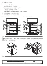
Operating and signalling parts .................................... « 16
7.2
Circuit-breaker closing and opening procedures ....... « 17
7.3
Racking-in/out operation ............................................... « 18
8.
Maintenance ........................................................
« 19
8.1
Warning ......................................................................... « 19
8.2
Maintenance program .................................................. « 20
8.3
Maintenance operations ............................................... « 20
8.3.1
Preliminary operations .................................................. « 20
8.3.2
General inspection of the circuit-breaker ..................... « 21
8.3.3
Checking contact wear ................................................ « 21
8.3.4
Operating mechanism maintenance ............................ « 22
9.
Measures to be taken for any operating
anomalies ............................................................
« 23
10.
Accessories .........................................................
« 24
10.1
Electrical accessories ................................................... « 24
10.2
Mechanical locks ........................................................... « 27
10.3
Spare parts and retrofitting .......................................... « 28
11.
Protection releases - General notes ................... « 29
11.1
Safety notes .................................................................. « 30
11.1.1 Notes for dielectric stiffness tests ................................. « 30
11.2
Abbreviations and notes ........................................
page
30
11.2.1 Abbreviations ................................................................ « 30
11.2.2 Notes ............................................................................. « 30
12.
SACE PR121/P Release - Identification ............
« 31
12.1
Standard ....................................................................... « 31
12.2
Specifications ................................................................ « 31
12.2.1 General .......................................................................... « 31
12.2.2 Electrical characteristics ............................................... « 31
12.2.2.1 Self-supply .................................................................... « 31
12.2.2.2 Auxiliary power supply ................................................. « 31
12.2.3 Environmental characteristics ....................................... « 32
12.2.4 Communication bus ...................................................... « 32
12.2.5 Protection functions ...................................................... « 32
12.2.5.1 Calculating the RMS ..................................................... « 32
12.2.5.2 Measuring function ....................................................... « 32
12.2.5.3 Watchdog ..................................................................... « 32
12.2.6 Description of the protection functions ........................ « 33
12.2.6.1 Protection “L” ................................................................ « 33
12.2.6.1.1 Thermal memory “L” ...................................................... « 33
12.2.6.2 Protection “S” ............................................................... « 33
12.6.2.2.1 Thermal memory “S” ...................................................... « 33
12.2.6.3 Protection “I” ................................................................. « 33
12.2.6.4 Protection “G” ............................................................... « 33
12.2.6.5 Protection against instantaneous short-circuit "Iinst" .... « 33
12.2.7 Summary table of protections ...................................... « 34
12.2.8 Table of measurements ................................................ « 34
12.2.9 Trip curves .................................................................... « 35
12.2.9.1 Trip curves for functions L-I .......................................... « 35
12.2.9.2 Trip curves for functions L-S(t=k/I
2
)-I ........................... « 35
12.2.9.3 Trip curves for functions L-S(t=k)-I .............................. « 36
12.2.9.4 Trip curves for function G ............................................. « 36
12.3
Other functions .............................................................. « 37
12.3.1 Indication of the cause of the trip and trip test button . « 37
12.4
Putting into service ........................................................ « 37
12.4.1 Connections .................................................................. « 37
12.4.2 CS and TC connection check ...................................... « 37
12.4.3 Current sensor connection for external neutral ............ « 37
12.5
User interface ................................................................ « 37
12.5.1 Trip Test ......................................................................... « 38
12.5.2 Initial settings ................................................................. « 38
12.5.3 Changing protection functions ..................................... « 38
12.5.3.1 Example of settings ....................................................... « 38
12.5.4 PR121/P default settings ............................................... « 39
12.6
Operating instructions / Operation in service .............. « 39
12.6.1 Neutral adjustment ....................................................... « 39
12.6.2 Neutral adjustment specifications ................................ « 39
12.6.3 Replacing an electronic release ................................... « 39
12.7
Definition of the alarms and signals for the
PR121/P unit .................................................................. « 40
12.7.1 Optical signals ............................................................... « 40
12.7.2 Troubleshooting ............................................................ « 41
12.7.3 In the case of a fault ...................................................... « 41
12.8
Accessories ................................................................... « 41
12.8.1 ABB SACE PR010/T test and configuration unit .......... « 41
12.8.2 BT030 communication unit ............................................ « 41
12.8.3 PR021/K and HMI030 units ........................................... « 41
12.8.4 PR030/B power supply unit .......................................... « 41
13.
SACE PR122/P Release - Identification ............
« 42
13.1
Standard ....................................................................... « 42
13.2
Specifications ................................................................ « 42
13.2.1 General .......................................................................... « 42
13.2.2 Electrical characteristics ............................................... « 43
13.2.2.1 Self-supply .................................................................... « 43
13.2.2.2 Auxiliary power supply ................................................. « 43

