L2234
Emax
130/158
Model
Scale
Page No.
Doc. No.
Apparatus
1SDH000460R0002
L2778
16.4.4
Description of the information given by the Data Logger system
16.4.4.1 Combination of devices for reading/setting data from the Data Logger system
By connecting to the release's outside bus, you can set certain data logger parameters, triggers or commands, or read certain types and sequences
of data in its memory.
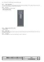
The combinations of devices and the consequent software combinations that enables these functions are as follows:
1) PR122/P + BT030+SD-Pocket
2) PR122/P + PR120/D-M + SD-Testbus or remote system
3) PR122/P+ PR120/D-BT + SD-Pocket
4) PR123/P + BT030+SD-Pocket
5) PR123/P + PR120/D-M + SD-Testbus or remote system
6) PR123/P+ PR120/D-BT + SD-Pocket
7) PR122/P + PR010/T *
8) PR123/P + PR010/T *
* With these combinations it is impossible to download sequences of stored data
In this manual, the term "from the system" is used to define both the operations that are carried out using one of the combinations with SD-Pocket
or SD-Testbus, and the operations that involve connecting to a remote system.
16.4.4.2
Access to saved data from the system
When the event associated with the stop event occurs or a stop command is received, the following data are saved in the recording block:
•
Data logger Trigger, which indicates the type of stop event (trigger) that has prompted the stoppage of the data logger;
•
Time-stamp of the stop event (trigger) (day/hour + minutes/seconds/milliseconds)(4 words);
•
Data logger max file, which indicates which is the max file with consistent data;
•
Data logger max address, which indicates the max address number of a block with consistent data.
The following information is recorded in the block for each sampling period:
1.
current sample L1
2.
current sample L2
3.
current sample L3
4.
current sample Ne
5 . voltage sample U12
6 . voltage sample U23
7 . voltage sample U31
8 . digital inputs/outputs (among 16 possible options, e.g. inputs/outputs for Zone Selectivity, PR120/K contact status, ...)
9. alarms1 (among 16 possible options, e.g. L timing, G alarm, Prealarm)
10. alarms2 (among 16 possible options, e.g. UF timing, OV timing, Frequency error, RP timing)
11. trips (among 16 possible options, e.g. tripping of L, S, I, G, UV, OF, ...)
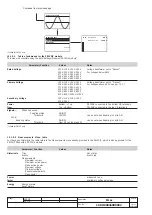
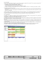
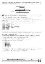
Maximum recording time is established by the sampling frequency set only, as described in the table in paragraph 16.4.2.2; recording time may
be lower than maximum time attainable when the sum of stopping delay and time elapsing between a restart trigger and a trigger is lower than
the maximum value, as described in the figure below:
If the parameters relating to the data logger are changed while it is operating, the recording underway is terminated and a new recording
begins (after a restart trigger command) on the basis of the new parameters.
Recording time
Stopping delay
Restart Trigger
Trigger
Maximum recording time

