L2234
Emax
109/158
Model
Scale
Page No.
Doc. No.
Apparatus
1SDH000460R0002
L2778
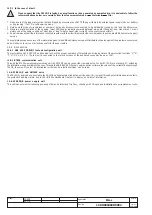
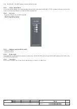
14.6.2 Electrical signals
K51/p1...p4
Programmable electrical signals if the PR120/K module or the PR021/K unit are installed and there is an auxiliary power supply.
K51/p1...p8
Programmable electrical signals if the PR021/K unit is installed and there is an auxiliary power supply.
Pressing the "i Test" key enables you to reset the activated contacts.
Signalling
Description
•The prealarm threshold has been exceeded; one or more phases with current values in the range
0.9xI
1
< I < 1.05xI
1
(on the Ne it depends on the selection made; for instance, at 50% the values are halved);
•Presence, between two or three phases, of unbalance above the value programmed for the "U" protection,
Warning
(yellow) led
with protection trip disabled;
• Presence of distorted wave form with form factor> 2.1;
•Contact wear greater than 80% (and less than 100%);
•WARNING Threshold I
w
exceeded;
•Circuit-breaker state error;
•Frequency out of range;
•Configuration error;
•Settings inconsistency.
Warning
Led (yellow 0.5Hz) •WARNING threshold of relay’s internal temperature exceeded.
Warning
Led (yellow 2Hz)
•ALARM threshold of relay’s internal temperature exceeded.
• Presence of overload on one or more phases with current values I >1.3 I1 (timing protection “L”)
(on the Ne it depends on the selection made; for instance, at 200% the values are doubled)*;
• Timing in progress for protection function S;
• Timing in progress for protection function G;
Alarm
(red) led
• Timing in progress for the voltage (UV, OV, RV), frequency (OF, UF) protection functions;
• Timing in progress for the reverse active power protection function (RP);
• Timing in the case of unbalance between the phases (protection U) above the value set in the configuration
with protection trip set to on;
• Contact wear = 100%;
• Rating Plug disconnected;
• Trip Coil (TC) disconnected;
• Key plug error;
• Current sensors disconnected;
• Installation error.
* The IEC 60947-2 Standard defines the timing threshold L for current: 1.05 < I < 1.3 I1.
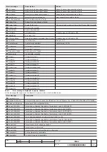
14.6.3 Table of error and warning messages
All the messages which can be shown on the display relating to incorrect configurations, generic alarms or deriving from the protection functions
and linked to useful information are described below.
The following symbols in the warning signals have the following meanings:
= Warning signal / Protection in alarm mode, with no trip (trip=off)
= Protection in alarm mode, with trip at end of delay (trip=on)
= Information, no action, except for displaying by the relay.
Error message
Description
Notes
Harmonic dist.
Harmonic distortion alarm
Busbar currents with form factor > 2.1
Contact wear
Alarm for contact wear
Contact wear = 100%
G (TRIP OFF)
Alarm for protection G
Gext (TRIP OFF)
Alarm for protection Gext
T Alarm
Alarm for protection T
Temperature outside range
T (TRIP OFF)
Alarm for protection T
U Alarm
Alarm for protection U
Protection U delay counting down
UV Alarm
Alarm for protection UV
OV Alarm
Alarm for protection OV
RV Alarm
Alarm for protection RV
RP Alarm
Alarm for protection RP
UF Alarm
Alarm for protection UF
OF Alarm
Alarm for protection OF
Load LC1
Alarm for load control LC1
Load LC2
Alarm for load control LC2
L1 Sensor
Alarm for L1 phase current sensor
Phase L1 sensor disconnected or faulty
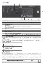
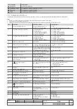
14.6 Definition of alarms and signals in the PR123/P unit
14.6.1 Optical signals


