76
DPA 2 50 S 4 50 - 2 50 K W
O P ER AT I N G M A N UA L
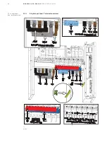
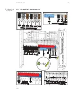
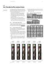
MAINS INPUT CABLE
UPS TERMINAL
BYPASS INPUT CABLE
UPS TERMINAL BYPASS
Phase L1
X3.1:L1
Phase L1
X4:L1
Phase L2
X3.2:L2
Phase L2
X4:L2
Phase L3
X3.3:L3
Phase L3
X4:L3
Neutral
X6:N
Neutral
N/N
GROUND (EARTH)
X7:PE
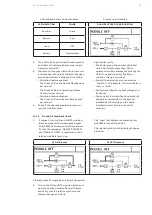
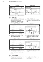
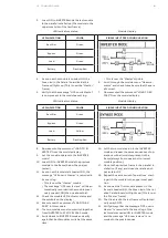
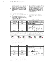
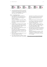
There is a cable-fixing rail below the connection terminal of the UPS to ensure that the cables have been
fastened properly. Keep the phase rotation in a clockwise direction
9.4.2
Output connections
NOTE
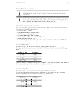
TO ENSURE CORRECT OPERATION OF THE UPS, THE LOADS CONNECTED TO THE OUTPUT MUST NOT
EXCEED THE HARMONIC CURRENTS LEVELS PERMITTED IN IEC 61000-3-2 (load
≤
16 A),
IEC 61000-3-12 (16 A < load
≤
75 A), or IEC/TS 61000-3-4 (load >75 A); IF THE INDICATED VALUES ARE
EXCEEDED PLEASE CONTACT THE MANUFACTURER
NOTE
FOR ASYMMETRIC LOADS REQUIRING THE CIRCULATION OF A.D.C CURRENT HIGHER THEN 10% OF THE
NOMINAL CURRENT, PLEASE CONTACT THE MANUFACTURER.
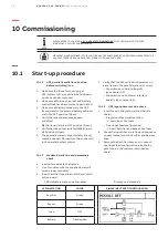
To ensure protection of the personnel during the installation of the UPS make sure that the connec-
tions are performed under the following conditions:
• No mains voltage is present
• All Loads are shut down and disconnected
• UPS is shut down and voltage-free
• UPS Modules are fitted in correct position
• Maintenance Bypass Q1 is open and in the OFF position
• First of all connect the ground-wire to the terminal X7-PE (PE).
9.4.2.1 Load connection
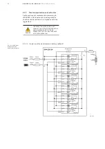
To achieve correct output cabling and protection, please refer to chapter 9.3.
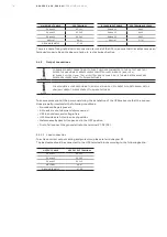
The load cable should be connected to the UPS terminal block according to the following table:
OUTPUT CABLE
UPS OUTPUT TERMINAL
Phase L1
X2.1:L1
Phase L2
X2.2:L2
Phase L3
X2.3:L3
NEUTRAL
X6:N
GROUND (EARTH)
X7:PE


