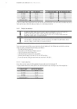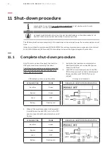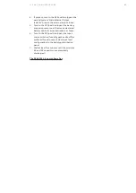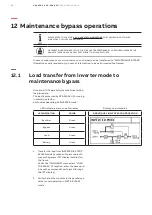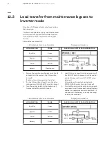
82
DPA 2 50 S 4 50 - 2 50 K W
O P ER AT I N G M A N UA L
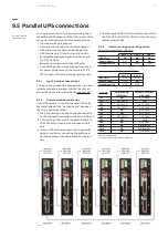
Only one Master module must be present in
the complete parallel system when all output
isolators Q2 are in the ON position (closed)!
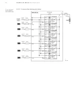
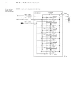
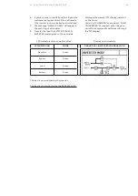
22. Repeat the same series of operations with all
modules present in all frames of the parallel
system.
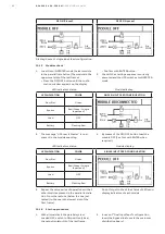
23. At the end of the start-up procedure (all mod-
ules loaded in INVERTER mode and all out-put
switches Q2 in ON position), only the Green
led present in the Parallel Interface board in-
side the first frame (The Master one) is ON.
All other Leds present in this and other paral-
lel boards must be OFF.
10.1.7 Battery connection and check
1. Carefully check the battery polarity and volt-
age.
2. Only if the battery polarity and voltage are
correct insert the external battery fuses/turn
to “ON” position the breakers.
3. Switch to ON position (close) the frame/s
battery breakers related to the inserted
modules.
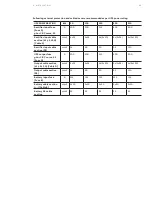
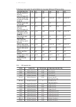
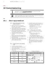
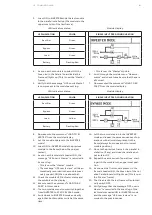
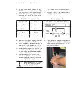
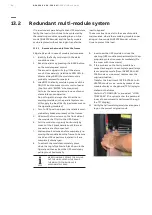
LED indicators status on all modules
Display on all modules
LED INDICATION
COLOR
SINGLE/DUAL INPUT FEED CONFIGURATION
Rectifier
Green
Bypass
Green
Load
Green
Battery
Green
Wait up to 2 minutes until the battery is correctly
recognized by all modules and the relative Led in-
dicators all turn Green.
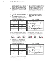
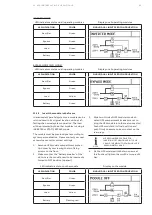
The modules are now recharging the batteries,
the relative symbols on the display change as fol-
lows (Battery filling from bottom to top):
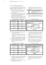
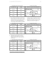
4. If possible turn to OFF position (open) the
general mains Rectifier Line isolator and
verify that all modules in the parallel system
start operating in battery mode.
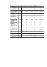
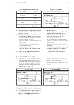
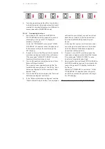
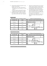
LED indicators status on all modules
Display on all modules
LED INDICATION
COLOR
DUAL INPUT FEED CONFIGURATION
Rectifier
Red
Bypass
Green (Red if single
input feed)
Load
Green
Battery
Flashing green
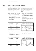
The modules are now operating in battery mode
to feed the load.
The relative battery symbols on the display
change as follows (Battery emptying from top to
bottom).

