31
—
5 Control & monitoring
ONLY NLY PEOPLE TRAINED BY SERVICE
TECHNICIANS OF THE MANUFACTURER
OR HIS CERTIFIED SERVICE PARTNERS ARE
ALLOWED TO OPERATE ON THE CONTROL
PANEL WITH CLOSED DOORS.
ALL OTHER INTERVENTION ON THE UPS
SYSTEM SHOULD ONLY BE CARRIED OUT
BY SERVICE TECHNICIANS OF THE
MANUFACTURER
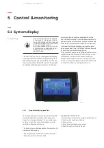
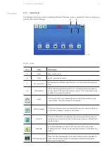
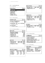
The user-friendly, touch screen graphical display
on the system level offers the opportunity of di-
rect monitoring the system status as well as the
status of each individual UPS module. The graphi-
cal display additionally provides all of the mea-
—
5.1 System display
—
5.1-1: System display
surements (module and system level) and the
user is able to transfer from double conversion to
bypass mode and vice-versa. All other commands
must be performed on the local UPS module con-
trol panel. With both displays in place (module
and system level), the UPS offers full user friendli-
ness without compromising rigidity.
The system display is also equipped with an alarm
indication bar that shows the main status of the
UPS system. If the unit is in normal condition
mode, a green light will be on; if an alarm occurs
on the unit, a yellow light will be on and if the unit
is in fault condition, a red light will be on.
—
5.1-1
5.1.1
Graphical display operation
For simple operation and configuration, the UPS
is optionally delivered with a microprocessor
based touch screen display. The navigation, pro-
cedures and the features of the display are de-
tailed in subsequent sections.
The touch screen display enables the operator to
perform the following:
• Check operational status and measurements
• Execute operational commands
(PASSWORD PROTECTED)
• Monitor the power flow through the UPS system
• Check events and alarm history
• Silence alarms
• Adjust programmable parameters
• Check the status of the batteries
5 CO N T R O L & M O N I TO R I N G

