39
3
2
1
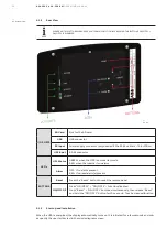
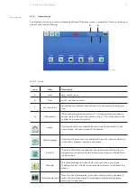
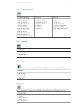
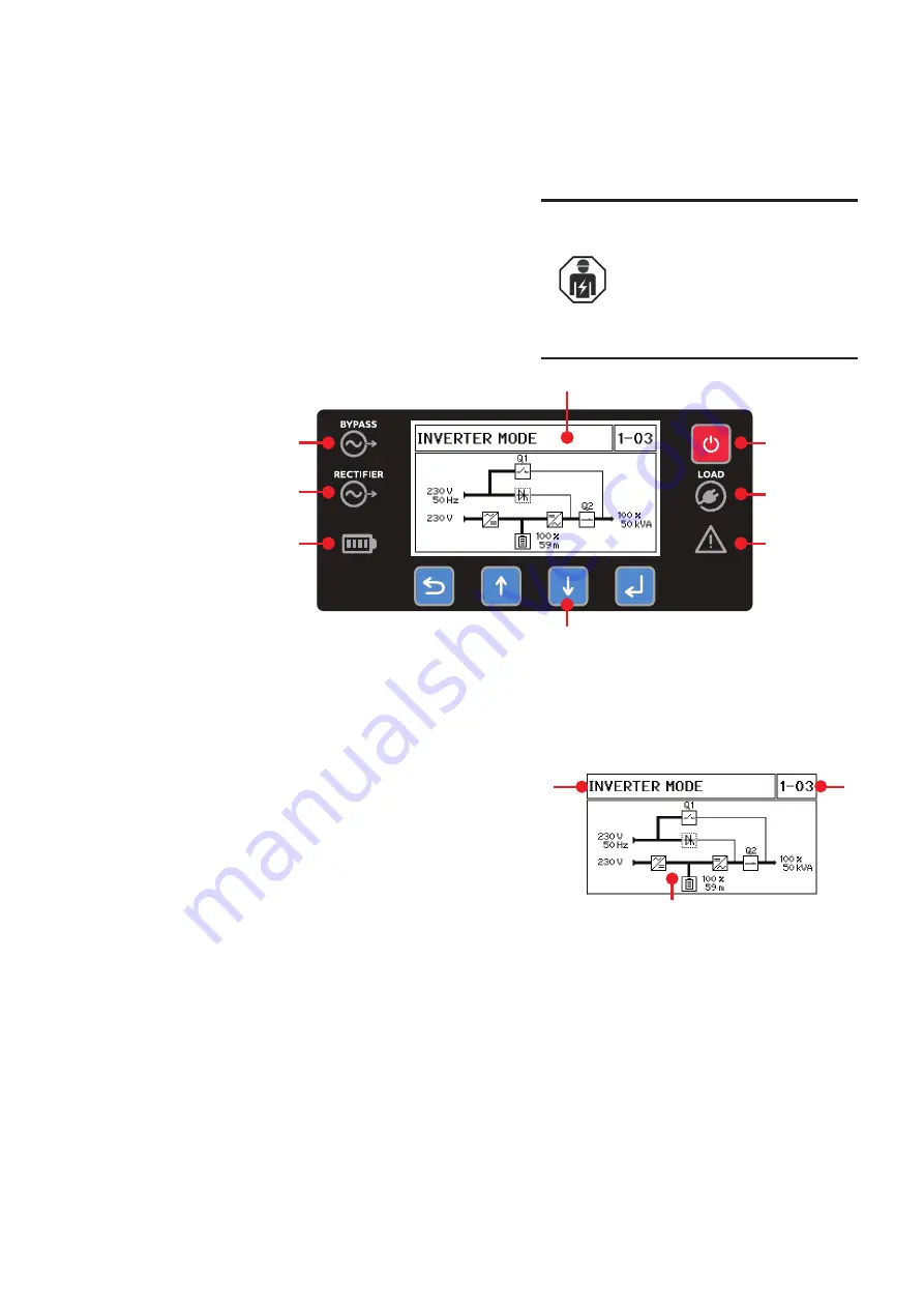
DISPLAY
ON/OFF
OUTPUT LED
ALARM LED
BYPASS LED
RECTFIER LED
BATTERY LED
CONTROL BUTTONS
The DPA 250 S4 UPS module has a control panel
consisting of:
• LCD display
• Power ON/OFF button
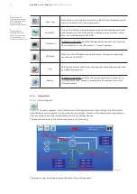
• Control and navigation buttons
• Led status indicators
—
5.2 Control panel UPS module
—
5.2-1: UPS module
control panel
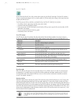
ONLY PEOPLE WHICH HAVE BEEN
TRAINED BY SERVICE TECHNICIANS OF
THE MANUFACTURER OR HIS CERTIFIED
SERVICE PARTNERS ARE ALLOWED TO
OPERATE ON THE CONTROL PANEL WITH
CLOSED DOORS.
ALL OTHER INTERVENTION ON THE UPS
SYSTEM SHOULD ONLY BE CARRIED OUT
BY SERVICE TECHNICIANS OF THE
MANUFACTURER
—
5.2-1
5.2.1
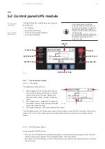
Control panel elements
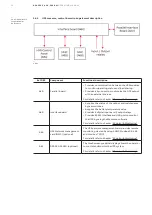
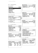
The display has three sections:
1. Mimic diagram of the UPS module showing
the rectifier, battery, static bypass, inverter
status and the input, bypass, battery and
output measurements : voltage, frequency,
power
2. UPS module status: module off, module dis-
connected, inverter mode, bypass mode, bat-
tery mode, stand-by mode
5.2.1.1 LCD display
—
5.2.1.1-1
—
5.2.1.1-1: Control
panel elements
3. UPS module location : UPS frame and module number
The LCD display goes into “Screensaver mode” by turning the screen off after 5 minutes if the control
panel is not in use. The screensaver mode is deactivated if any control button is pressed or alarm
popup.
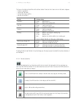
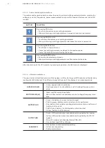
By pressing the ON/OFF button
• Start up : the UPS Module turns ON by starting the normal operations and going into the “On-line”
mode if main input is applied. The LCD display shows “Load on inverter”
• Shut-down : the UPS Module turns OFF if the button is pressed for 3 seconds and the user confirms
the shut-down.
5.2.1.2 ON/OFF power button
5 CO N T R O L & M O N I TO R I N G

