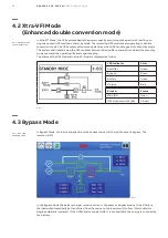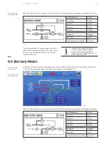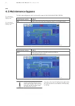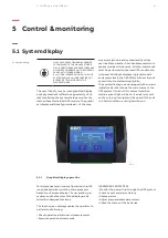
34
DPA 2 50 S 4 50 - 2 50 K W
O P ER AT I N G M A N UA L
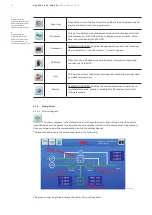
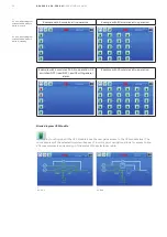
Event log
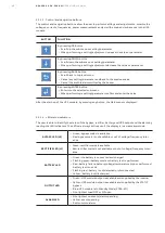
Directs the user to the Event log screen where the stored events and
alarms are shown in chronological order.
Measures
This button directs to the Measures screen which displays electrical
measurements of the UPS such as voltages, power, currents, auton-
omy, etc. Not Needed for XTRA VFI.
Command
PASSWORD NEEDED : enables the operator to execute the following
basic operations: “Load to inverter”, “Load to bypass”.
UPS Data
Directs to the UPS data screen which gives information regarding
the identity of the UPS.
User
This button directs to the User settings sub-menu allows to set time
and date, language, etc.
Service
PASSWORD NEEDED : enables the service technician to perform re-
stricted commands, enable or disable Xtra VFI and set restricted
UPS parameters.
1
2
1
The password for
accessing the command
menu is different than
the one needed to
access the service menu
2
The password for
accessing the service
menu is different than
the one needed to ac-
cess the command menu
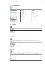
5.1.5 Navigation
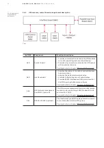
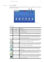
The mimic diagram is the default screen. It shows the power flow through the UPS system
(standalone as well as parallel configuration) and indicates its status. This diagram can be accessed
from any screen using the corresponding icon in the display header.
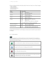
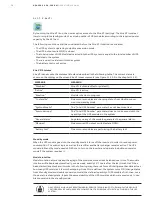
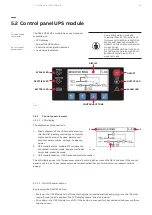
The interactive blocks in the mimic diagram are the following:
5.1.5.1 Mimic diagram
—
5.1.5.1-1
STATIC
BYPASS
RECTIFIER
INVERTER
BATTERY
The green connecting lines indicate the power flow in the system

