26
DPA 2 50 S 4 50 - 2 50 K W
O P ER AT I N G M A N UA L
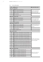
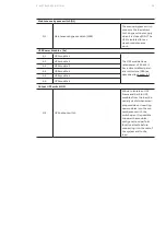
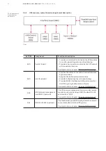
3.4.6
UPS measure, control & monitoring element description
—
3.4.6-1
—
3.4.6-1: UPS measure,
control & monitor-
ing elements
Ref DES
Component
Functional description
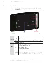
A40
Parallel board
• Provides communication between the UPS modules
to monitor operating status and load sharing.
• Provides a Sync port to synchronize the UPS output
with an external sources.
For details refer to chapter "5 Control & Monitoring"
A60
Interface board
• Acquires the status of the output and maintenance
bypass switches
• Acquires the battery temperature value
• Provides 5 digital inputs and 5 output relays
• Provides RS232 interface and USB port to monitor
the UPS by using the Wavemon software
For details refer to chapter "5 Control & Monitoring"
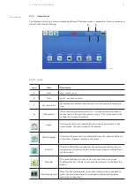
A65
UPS Network management
card (NMC) (optional)
The UPS network management card provides remote
monitoring via web by using SNMP, Modbus RS-485
and Modbus TCP/IP
For details refer to chapter "5 Control & Monitoring"
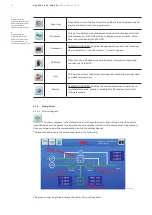
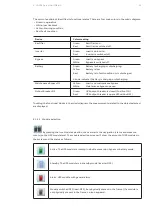
A61
DPA 250 S4 HMI (optional)
The touchscreen graphical display allows the operator
to control and monitor the UPS system.
For details refer to chapter "5 Control & Monitoring"

