II K 4-34
Overview of Software
1 = Speed Contr
/
2 = Torque Contr
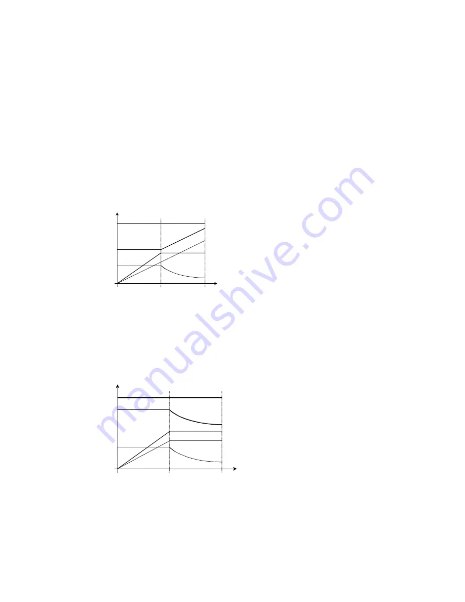
Depending on the application involved, however, a
constant torque is also required in the field weakening
range
(Torque-Controlled Mode (3.14) = Torque
Contr)
. For this purpose, the armature current has to
be increased in this range, in order to compensate for
the reduced field flux. This can be done only if the
parameterisation permits a current increase, i.e. the
current limit of Parameter
Arm Cur Max (3.02)
is not
reached.
If the current limitation level is greater than rated
armature current
(Arm Cur Max (3.02) > 100 %)
then
power converter and motor have to have been dimen-
sioned for this overload mode.
This procedure is also employed in
speed-control-
led
drives.
Armature Current
(1.01 / …Max 3.04 / …Act 3.02)
Torque Act (3.23)
Power Act (3.21)
Armature Voltage
(1.02 / …Act 3.03)
Field Current
(1.03 / …Act 4.02)
6SHHG&RQWUROOHG7RUTXH&RQWUROOHG
n
armature control range
field weakening range
Base Speed
(1.05)
Max Speed
(1.06)
3 = Cur Contr
In a
current-controlled
mode (
Cur Contr Mode
(3.14) = Cur Contr)
, the system is controlled inde-
pendently of the speed in terms of the current refer-
ence value. The motor’s torque, however, decreases
in the field weakening range in proportion to the speed
increase 1/n.
Torque Act (3.23)
Armature Current
(1.01 / …Act 3.02)
Power Act (3.21)
Armature Voltage
(1.02 / …Act 3.03)
Field Current
(1.03 / …Act 4.02)
n
&XUUHQW&RQWUROOHG
armature control range
field weakening range
Base Speed
(1.05)
Max Speed
(1.06)
4 = Speed + Torque
Depend on application in speed control mode a pre-
control of torque is required to have the drive more
dynamic. The torque reference is selected in
Torque
Ref Sel (3.15)
.
Torque references
coming from
speed controller output
and from reference select-
ed in
Torque Ref Sel (3.15)
are added.
5 = Lim Sp Ctr („MIN“)
Speed control with external torque limitation.
Example of an overload parameterization routine
by means of
external torque limitation.
e.g.
Motor nominal current
= 170 A
Overload
= 200%
Speed reference
= analogue input AI1
External Torque Limit.
= analogue input AI2
Parameters affected
Arm Cur Nom (1.01)
=
170 A
Arm Cur Max (3.04)
=
200%
Overload Time (3.05)
= 60 s
(*)
Recovery Time (3.06)
= 900 s (*)
Torque Lim Pos (3.07)
=
200%
Torque Lim Neg (3.08)
=
-200%
Cur Contr Mode (3.14)
=
Lim Sp Ctr
é
external
limitation
Torque Ref Sel (3.15)
=
AI2
or
Macro depend
é
variable
limitation
Speed Ref Sel (5.01)
=
AI1
or
Macro depend
AI2 Scale 100% (6.03)
=
5.00 V
(10 V = 200%)
Overload variable
settable between
0…200 % (0…10 V)
(*) The particulars given here for Overload Time and
Recovery Time are to be construed as examples only.
The actual figures will depend on the overload with-
stand capabilities of the drive components (motor and
power converter), and must be covered by the plan-
ning work.
Содержание DCS 400
Страница 1: ...II K 1 1 DCS Thyristor power converter for DC drive systems 20 to 1000 A 9 to 522 kW Manual DCS 400 ...
Страница 24: ...II K 3 14 Technical data ...
Страница 29: ...II K 4 5 Overview of Software ...
Страница 158: ...II K 6 36 Operating Instructions ...
Страница 181: ...II K B 1 Appendix B Declaration of conformity ...
Страница 190: ...Notices ...
Страница 191: ...Notices ...


