


II K 4-26
Overview of Software
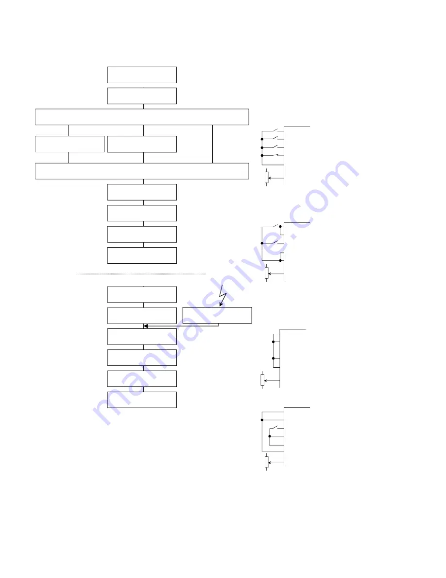
Fig. 4.4/2:
Switch-off sequence of DCS 400
Minimal circuitry for the drive logic
All digital inputs of the drive logic are
edge-sensitive
,
i.e. the function concerned will be executed only if
there is a
signal change
from 0
ÿé
1 or 1
ÿéÿ
0.
Drive is controlled using two commands (
On
and
Run
separated
)
On
Run
Reset
+24V
Speed Ref
Eme Stop
On
Run
Reset
+24V
Speed Ref
Eme Stop
On
Run
Reset
+24V
Speed Ref
Eme Stop
Ready for On
Recommended circuitry
On and Run can be control-
led edge-sensitively. Stop
Mode (2.03) and Eme Stop
Mode (2.04) can be used.
Drive is controlled using one command (
On
and
Run
jointly
)
Possible circuitry
On and Run can be control-
led edge-sensitively.
Stop Mode (2.03) and Eme
Stop Mode (2.04)
cannot
be
used, however.
You want the drive to be
switched on automatically
after the electronics supply has been switched on.
1. Not possible
Since no edge-sensitive sig-
nals can be generated. The
drive will not start up even
after the electronics supply
has been switched on.
2. Possible circuitry
Since the requisite edges can
be generated by means of a
Rdy On
signal when the elec-
tronics supply is switched on
or after a reset following a
fault. Stop Mode (2.03) and
Eme Stop Mode (2.04)
can-
not
be used, however.
Danger
:
Acknowledgement
of faults
occurring will
switch on
the
drive
directly
.
Switch off the drive via
6723
and
2))
command
STOP command
581
1 ==> 0
5DPS7RUTXH/LP&RDVW
Stop Mode
Brake via Ramp until
=HUR
6SHHG
= 1
Brake at Torque Limitation
until
=HUR6SHHG
= 1
Stop the current controller
alpha = 150° el (inverter stability limit)
6ZLWFKWKHGULYH2))
2))
command
ON/OFF 1 ==> 0
Delay time
(until arm. current = 0)
Open the main contactor
0DLQ&RQW2Q
= 0
Switch off fan
)DQ2Q
= 0
'ULYHLV2))
6ZLWFKWKHGULYH2))
during RUN command is still on:
Switch off the drive via
2))
command
Switch
212))
to off
ON/OFF 1 ==> 0 (RUN = 1)
Stop the current controller
(alpha = 150° el)
Delay time
(until arm. current = 0)
Open the main contactor
0DLQ&RQW2Q
= 0
Switch off fan
)DQ2Q
= 0
'ULYHLV2))
If drive trips in case of
)DXOWV
during operation
'&6
VZLWFK2))VHTXHQFH
6WRSWKHFXUUHQWFRQWUROOHU
On
Run
Reset
+24V
Speed Ref
Eme Stop
Содержание DCS 400
Страница 1: ...II K 1 1 DCS Thyristor power converter for DC drive systems 20 to 1000 A 9 to 522 kW Manual DCS 400 ...
Страница 24: ...II K 3 14 Technical data ...
Страница 29: ...II K 4 5 Overview of Software ...
Страница 158: ...II K 6 36 Operating Instructions ...
Страница 181: ...II K B 1 Appendix B Declaration of conformity ...
Страница 190: ...Notices ...
Страница 191: ...Notices ...