


Hardware description
45
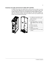
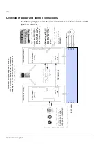
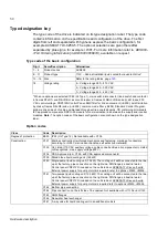
Connections and use of the I/O in the supply unit
The table and the figure below describe the connections and use of the I/O in the
supply unit. The use of I/O is fixed in the supply unit control program and the wiring
to RMIO terminals are made accordingly at the factory. The settings of the supply
control program and the connections of the supply unit I/O must not be changed by
the user.
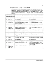
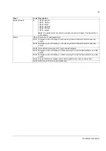
IO
Name
Use in the control program
Connected device / Purpose
RDCU standard I/O channel
AI1
Not in use
Not in use as default.
Not in use as default.
A12
Not in use
Not in use as default.
Not in use as default.
AI3
Not in use
Not in use as default.
Not in use as default.
DI1
ALARM / FAULT
Overtemperature supervision: 1->0: Alarm.
0: Fault (after preset time delay).
LCL filter temperature sensors (in series)
DI2
ON / OFF
Supply module on/off control. 0->1: On.
0: Off.
Operating switch, control circuitry
DI3
ACK MAIN
CONTACTOR
Main breaker/contactor supervision. 1:
closed (enables supply unit start)
Contact in main breaker/contactor control
circuit
DI4
EARTH FAULT
Ground fault supervision. Can be activated or
inactivated by parameter. 1: No fault. Not in
use as default.
Insulation monitoring device (Q954)
DI5
ALARM / FAULT
Supervision of cooling unit. Can be activated
or inactivated by parameter. 1->0: Alarm.
0: Fault (after preset time delay). Not in use
as default.
Cooling unit monitoring circuit. Not in use but
hard-wired to +24 V DC of RDCU when no
optional cooling unit is in use.
DI6
RESET
Supply module reset. 1: Reset.
Not connected as default. Fault reset can be
given from control panel.
DIIL
Not in use
Not in use as default.
Not in use as default.
RO1
CHARGING
On/off control of charging contactor. 1: On.
Charging circuit control relay
RO2
LCU ON / OFF
Liquid cooling unit on/off control. 1: On.
Cooling unit control relay. Not connected
when no optional cooling unit (+C139, +C140
or +C141) is in use.
RO3
MAIN
CONTACTOR
CONTROL
Main breaker/contactor control. 1: On.
Breaker control circuit
Содержание ACS800-17LC
Страница 1: ...ABB industrial drives Hardware manual ACS800 17LC Drives 55 to 5200 kW ...
Страница 4: ......
Страница 10: ...Update notice 6 ...
Страница 18: ...Table of contents 12 ...
Страница 26: ...Safety instructions 20 ...
Страница 32: ...Introduction to the manual 26 ...
Страница 60: ...Hardware description 54 ...
Страница 74: ...Mechanical installation 68 ...
Страница 114: ...Electrical installation 108 ...
Страница 142: ...Maintenance 136 ...
Страница 150: ...Internal cooling circuit 144 ...
Страница 179: ...Dimensions 173 Frame sizes R7i R7i and R8i R8i bottom entry exit ...
Страница 180: ...Dimensions 174 Frame sizes R7i R7i and R8i R8i marine units C121 ...
Страница 182: ...www abb com drives www abb com drivespartners Contact us 3AUA0000065339 Rev B EN 2016 06 07 ...


