


Start-up
111
Start-up
What this chapter contains
This chapter contains start-up instructions for the drive.
Start-up procedure
These instructions do not cover all start-up tasks of all possible variants of the drive,
just the basic steps. Always refer to the delivery-specific circuit diagrams when
proceeding with the start-up.
The designations in square brackets refer to the designations used in the circuit
diagrams.
Action
Additional information
Safety
WARNING!
Only qualified electricians are allowed to commission the drive. Read and follow the safety
instructions on the first pages of this manual. Neglecting the safety instructions can cause injury or death.
WARNING!
Ensure that the disconnector of the supply transformer is locked to open position ie, no voltage is,
or can be connected to the drive inadvertently. Check also by measuring that there is no voltage connected.
Checks with no voltage connected
Drive with main breaker (frame 2xRi+2xR8i and bigger units)
Check the current trip limits of the breaker preset at the factory.
General rule
Ensure the selectivity condition is fulfilled ie, the breaker trips at a lower
current than the protection device of the supplying network, and that the
limit is high enough not to cause unnecessary trips during the
intermediate DC circuit load peak at start.
Long-term current limit
As a rule of thumb, this should be set to the rated input AC current of the
drive.
Peak current limit
As a rule of thumb, this should be set to a value 3…4 times the rated
input AC current of the drive.
Check the settings of the relays and breakers/switches of the auxiliary
circuits.
Optional devices. See delivery
specific circuit diagrams.
Disconnect any unfinished or unchecked 230/115 V AC cables that lead
from the terminal blocks to the outside of the equipment.
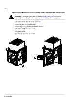
Frame 2×R8i and up: Enable the memory backup battery on the PPCS
branching units (APBU) by setting actuator 6 of switch S3 to ON. The
branching units are located on the supply and inverter module cubicle
swing-out frames.
By default, memory backup is
switched off to save the battery.
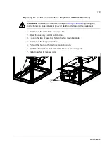
Fill up and bleed the internal cooling circuit. Ensure that the coolant can
flow freely in all cubicles. Start the cooling unit up.
Chapter
. For
drives with the optional cooling unit
(option codes +C140 or +C141), see
ACS800-1007LC User’s Manual
(3AFE68621101 [English]).
Содержание ACS800-17LC
Страница 1: ...ABB industrial drives Hardware manual ACS800 17LC Drives 55 to 5200 kW ...
Страница 4: ......
Страница 10: ...Update notice 6 ...
Страница 18: ...Table of contents 12 ...
Страница 26: ...Safety instructions 20 ...
Страница 32: ...Introduction to the manual 26 ...
Страница 60: ...Hardware description 54 ...
Страница 74: ...Mechanical installation 68 ...
Страница 114: ...Electrical installation 108 ...
Страница 142: ...Maintenance 136 ...
Страница 150: ...Internal cooling circuit 144 ...
Страница 179: ...Dimensions 173 Frame sizes R7i R7i and R8i R8i bottom entry exit ...
Страница 180: ...Dimensions 174 Frame sizes R7i R7i and R8i R8i marine units C121 ...
Страница 182: ...www abb com drives www abb com drivespartners Contact us 3AUA0000065339 Rev B EN 2016 06 07 ...