


Maintenance
130
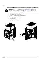
10. Unplug the fiber optic cable from the module.
11. Unplug the terminal block from the module.
12. Remove the module mounting screws (four at top, two at bottom).
13. Disconnect the DC output busbars from the module. Beware not to drop the
screws inside the module!
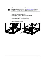
14. Assemble the module installation stand. See
Installing the installation stand
page
. Pay attention to the width: Select the right braces to match the width
of the stand to the width of the cubicle.
15. Fasten the module installation stand to the frame of the cubicle (2 × 5 screws).
Align the stand and the rails on which the module lies on in the cubicle. Adjust
the height of the feet.
Note:
Remove the cabinet hinge first if necessary.
WARNING!
The feet must lean on a solid floor. The cubicle may topple over when
the heavy module is pulled out if the stand is not supported properly.
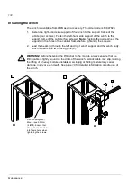
16. Fasten the lifting bar of the winch to the two module lifting holes.
WARNING!
Before fastening the lifting bar, always ensure that the lifting cable is
tightly wound on the drum of the winch. A slack cable may slip, making the lifting of a
heavy module unstable. A swinging or falling module may cause damage, injury or
even death. See
Use of the hand-operated winch
(page
)
for more detailed
information on safe use of the winch.
17. Pull the module out of cubicle onto the installation stand. Keep the pipes and
wires away from the sharp edges.
18. Winch the module up.
19. Remove the module installation stand.
20. Winch the module down and lay it on a pallet.
WARNING!
The module is heavy and its centre of gravity is high. The module
topples over easily. Never manoeuvre it in upright position untied. It is highly
recommended to lay the module on its side before moving the pallet.
21. Move the pallet with the module aside.
22. Before installing a new module, check and service the quick connector through
which the AC output busbars or the cubicle connect to the module:
• Check the tightness of the motor cable connections at the quick connector:
70 N·m (52 lbf·ft).
• Clean all contact surfaces of the quick connector and apply a layer of suitable
joint compound eg, Isoflex® Topas NB 52 from Klüber Lubrication, onto them.
23. Install new module in reverse order.
Содержание ACS800-17LC
Страница 1: ...ABB industrial drives Hardware manual ACS800 17LC Drives 55 to 5200 kW ...
Страница 4: ......
Страница 10: ...Update notice 6 ...
Страница 18: ...Table of contents 12 ...
Страница 26: ...Safety instructions 20 ...
Страница 32: ...Introduction to the manual 26 ...
Страница 60: ...Hardware description 54 ...
Страница 74: ...Mechanical installation 68 ...
Страница 114: ...Electrical installation 108 ...
Страница 142: ...Maintenance 136 ...
Страница 150: ...Internal cooling circuit 144 ...
Страница 179: ...Dimensions 173 Frame sizes R7i R7i and R8i R8i bottom entry exit ...
Страница 180: ...Dimensions 174 Frame sizes R7i R7i and R8i R8i marine units C121 ...
Страница 182: ...www abb com drives www abb com drivespartners Contact us 3AUA0000065339 Rev B EN 2016 06 07 ...