


Hardware description
29
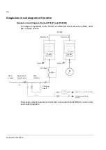
Example circuit diagram (frame 2×R8i+2×R8i)
This diagram represents a frame 2×R8i+2×R8i drive
with
out any EMC, du/dt filter or
brake options. Both the supply unit and the inverter unit consist of two parallel frame
R8i converter modules.
The supply unit and inverter unit have their own control boards (RDCU control units)
and control programs.
M
Ground fault monitoring
(+Q954)
230 V AC or 115 V AC (+G304)
M
DC bus
M
3~
230/115 V AC
230/115 V AC
Main
supply
M
M
230/115 V AC
230/115 V AC
Charging
circuit
Supply unit
Inverter unit
Main
breaker
LCL filter
Содержание ACS800-17LC
Страница 1: ...ABB industrial drives Hardware manual ACS800 17LC Drives 55 to 5200 kW ...
Страница 4: ......
Страница 10: ...Update notice 6 ...
Страница 18: ...Table of contents 12 ...
Страница 26: ...Safety instructions 20 ...
Страница 32: ...Introduction to the manual 26 ...
Страница 60: ...Hardware description 54 ...
Страница 74: ...Mechanical installation 68 ...
Страница 114: ...Electrical installation 108 ...
Страница 142: ...Maintenance 136 ...
Страница 150: ...Internal cooling circuit 144 ...
Страница 179: ...Dimensions 173 Frame sizes R7i R7i and R8i R8i bottom entry exit ...
Страница 180: ...Dimensions 174 Frame sizes R7i R7i and R8i R8i marine units C121 ...
Страница 182: ...www abb com drives www abb com drivespartners Contact us 3AUA0000065339 Rev B EN 2016 06 07 ...