


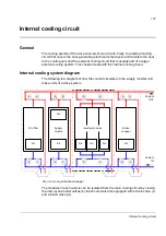


Internal cooling circuit
139
Filling up and bleeding the internal cooling circuit
Both the drive and coolant must be at room temperature before filling in the cooling
circuit.
WARNING!
Ensure that the maximum permissible operating pressure is not
exceeded. When necessary regulate the pressure to appropriate level by draining
excess coolant out of the system.
WARNING!
Bleeding of the cooling circuit is very important and has to be done with
great care. Air bubbles in the cooling circuit may reduce or completely block coolant
flow and lead to overheating. Let the air out of the cooling system while filling in
coolant and, e.g. after any power module replacements.
Drive line-ups with an ACS800-1007LC cooling unit
Follow the filling up and bleeding instructions in
ACS800-1007LC Cooling Unit
User’s Manual
(3AFE68621101 [English]).
Drive line-ups with a custom cooling unit
Notes:
• The bleed valves in the line-up are used only to vent the air from the circuit so that
it can be displaced by the coolant. The actual bleeding of the circuit must be done
via an external bleed valve installed at the highest point of the cooling circuit. The
most practical location for the valve is usually near or at the cooling unit.
• Observe the instructions given by the manufacturer of the cooling unit. Pay
special attention to filling up and bleeding the pumps properly as they may be
damaged if operated when dry.
• Draining propylene glycol into the sewer system is not allowed.
1. Open the bleed valve at the cooling unit.
2. Open the inlet, outlet and bleed valves of one drive cubicle.
3. Lead the bleed hoses into buckets or other suitable containers. Extend the
standard hoses if necessary.
4. Fill the circuit with coolant. For coolant specification, see below.
5. After the drive unit is filled up, coolant will start flowing from the bleed hose of the
drive cubicle. Let some coolant flow out before closing the bleed valve.
6. Close the inlet, outlet and bleed valves of the drive cubicle.
7. Repeat steps 2…6 for all drive cubicles in the line-up.
8. Open the inlet and outlet valves in all drive cubicles. Let any air remaining in the
system out through the bleed valve at the cooling unit.
9. Close the bleed valve at the cooling unit.
Содержание ACS800-17LC
Страница 1: ...ABB industrial drives Hardware manual ACS800 17LC Drives 55 to 5200 kW ...
Страница 4: ......
Страница 10: ...Update notice 6 ...
Страница 18: ...Table of contents 12 ...
Страница 26: ...Safety instructions 20 ...
Страница 32: ...Introduction to the manual 26 ...
Страница 60: ...Hardware description 54 ...
Страница 74: ...Mechanical installation 68 ...
Страница 114: ...Electrical installation 108 ...
Страница 142: ...Maintenance 136 ...
Страница 150: ...Internal cooling circuit 144 ...
Страница 179: ...Dimensions 173 Frame sizes R7i R7i and R8i R8i bottom entry exit ...
Страница 180: ...Dimensions 174 Frame sizes R7i R7i and R8i R8i marine units C121 ...
Страница 182: ...www abb com drives www abb com drivespartners Contact us 3AUA0000065339 Rev B EN 2016 06 07 ...