


Hardware description
28
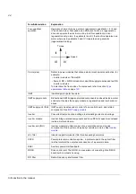
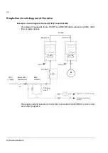
Single-line circuit diagram of the drive
Example circuit diagram (frames R7i+R7i and R8i+R8i)
This diagram represents frame R7i+R7i and R8i+R8i drives
with
out any EMC, du/dt
filter or brake options.
The supply unit and inverter unit have their own control boards (RDCU control units)
and control programs.
M
Ground fault monitoring
(+Q954)
230 V AC or 115 V AC (+G304)
DC bus
M
3~
230/115 V AC
M
230/115 V AC
Charging
circuit
Supply unit
Inverter unit
Main
contactor
LCL filter
Main switch
disconnector
Main
supply
Содержание ACS800-17LC
Страница 1: ...ABB industrial drives Hardware manual ACS800 17LC Drives 55 to 5200 kW ...
Страница 4: ......
Страница 10: ...Update notice 6 ...
Страница 18: ...Table of contents 12 ...
Страница 26: ...Safety instructions 20 ...
Страница 32: ...Introduction to the manual 26 ...
Страница 60: ...Hardware description 54 ...
Страница 74: ...Mechanical installation 68 ...
Страница 114: ...Electrical installation 108 ...
Страница 142: ...Maintenance 136 ...
Страница 150: ...Internal cooling circuit 144 ...
Страница 179: ...Dimensions 173 Frame sizes R7i R7i and R8i R8i bottom entry exit ...
Страница 180: ...Dimensions 174 Frame sizes R7i R7i and R8i R8i marine units C121 ...
Страница 182: ...www abb com drives www abb com drivespartners Contact us 3AUA0000065339 Rev B EN 2016 06 07 ...