


P. 44 - Chap. 7 Start-up and operation
G
B
CONFIRMED
pressing the K9-ENTER key
10
OPERATION
COMPLETED
CANCELLED
pressing the K4-ESC key
OPERATION
ABORTED
ESC
Each time a parameter is modified, the factory-set (default value) can be restored for the selected
compressor pressing the
K3-RESET
key
RESET
7.4.2.1
PASSWORD menu
Used to enter a password to enable particular functions (e.g. AUTORESTART) or to access protected
menus.
For enabling of the AUTORESTART function, contact the Manufacturer’s Customer Service
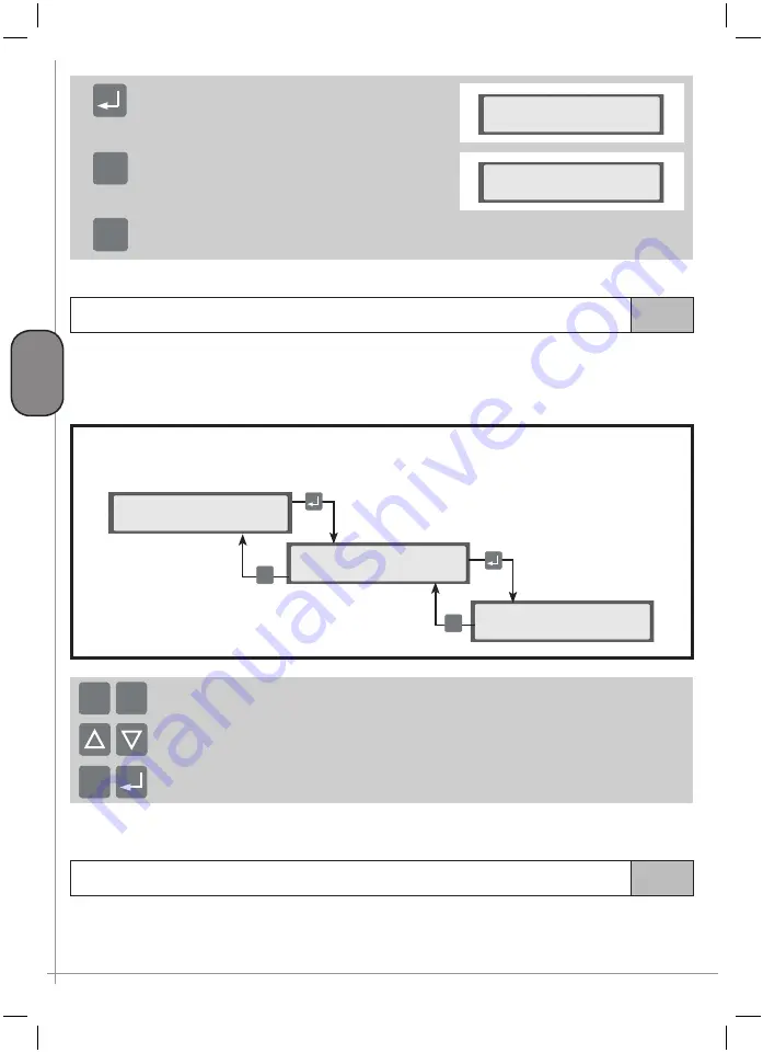
The password is inserted using:
Menu C
>PASSWORD
<
>
Enter password
<
Enter password:
0000
ESC
ESC
keys
K7
and
K8
to modify the flashing character; numbers and letters are displayed subsequently
the
K5
and
K6
keys to move to modification of the previous / next character
After inserting the password, this can be confirmed with the
K9-ENTER
key or cancelled with the
K4-ESC
key
ESC
+ -
If no other key is pressed, the password entered “expires” after five minutes with possibly display of a re-entry prompt.
7.4.2.2
MAINTENANCE menu
This menu is used to display short-term maintenance operations, the remaining service life of each component,
to reset the life counters of each component (where this function is enabled), to display compressor hours
of operation.
Содержание GENESIS Series
Страница 1: ...GENESIS FORMULA MODULO 5 5 15 kW USE AND MAINTENANCE HANDBOOK GB...
Страница 2: ......
Страница 11: ...IX FORMULA 15 kW BA 69 Fig 17 Fig 18 PC PE SPA CF FA PF CT TRL VR BF PS ES EV FU MA RA RO MP PP VA FO FO VS SS...
Страница 12: ...X MODULO 5 5 7 5 kW Fig 19 Fig 20 FO FD FA SS ES FU MA RA RO PP MP PC PE SCE SF VA EV BF VT TRL CT PF VS PS...
Страница 14: ...XII MODULO 15 kW BA 69 Fig 23 Fig 24 PS PP PF MA FU RA RO ES VA FO FD VS SS MP CF FA SCE PE PC TRL VR BF CT EV...
Страница 82: ...P 80 Chap 12 Diagrams G B 12 Diagrams Hydraulic pneumatic plant diagram 12 1...
Страница 84: ...P 82 Chap 12 Diagrams G B Power circuit wiring diagram 5 5 15 kW Machines without air dryer 12 2...
Страница 85: ...P 83 Chap 12 Diagrams G B Power circuit wiring diagram 5 5 15 kW Machines with air dryer 12 3...
Страница 86: ...P 84 Chap 12 Diagrams G B Power circuit wiring diagram 11 kW Machines with inverter 12 4...
Страница 87: ...P 85 Chap 12 Diagrams G B Auxiliary circuit wiring diagram 5 5 15 kW Machines without air dryer 12 5...
Страница 88: ...P 86 Chap 12 Diagrams G B Auxiliary circuit wiring diagram 5 5 15 kW Machines with air dryer 12 6...
Страница 89: ...P 87 Chap 12 Diagrams G B Auxiliary circuit wiring diagram 11 kW Machines with inverter 12 7...
Страница 90: ...P 88 Chap 12 Diagrams G B Wiring diagram for component location 5 5 15 kW Machines without air dryer 12 8...
Страница 91: ...P 89 Chap 12 Diagrams G B Wiring diagram for component location 5 5 15 kW Machines with air dryer 12 9...