


P. 53 - Chap. 7 Start-up and operation
G
B
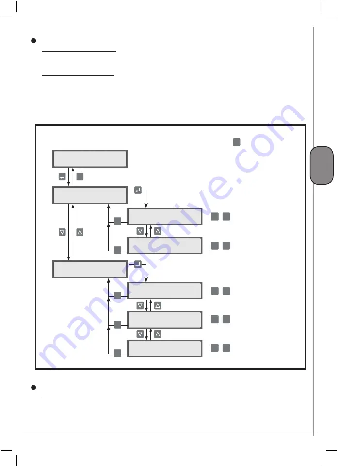
Pressures
MAX. OPERATING PRESS.:
The pressure above which the compressor starts to idle. The rated pressure
of the machine represents the upper limit of this value.
MIN OPERATING PRESS.:
The pressure below which the compressor restarts operation at full load
(supply of compressed air) or at which it restarts if it has stopped at the end of unload run (no supply
of air). This value must be set so that the minimum supply pressure to the pneumatic service points is
guaranteed, taking into account losses of head of the distribution system. The minimum pressure value
cannot be close to the maximum pressure by more than the factory setting (minimum difference).
Timings
UNLOAD RUN TIME:
This setting defines the time during which the compressor idles when there is no
demand for air from the network. At the end of this period, the compressor stops and is ready to start
again when network pressure has dropped below the minimum threshold value.
Press the K4 key to return to the
OPERAT. PARAMETERS
menu from the submenus
ESC
Menu G
>OPERAT. PARAMETERS <
>Pressures
<
Operating press.
Max:
xxx bar
ESC
Operating press.
Min:
xxx bar
ESC
>Timings
<
Unload run time
val.:
xxx min
ESC
Time DRAIN open
val.:
xxx min
ESC
ESC
+ -
Time DRAIN closed
val.:
xxx min
ESC
+ -
+ -
+ -
+ -
Содержание GENESIS Series
Страница 1: ...GENESIS FORMULA MODULO 5 5 15 kW USE AND MAINTENANCE HANDBOOK GB...
Страница 2: ......
Страница 11: ...IX FORMULA 15 kW BA 69 Fig 17 Fig 18 PC PE SPA CF FA PF CT TRL VR BF PS ES EV FU MA RA RO MP PP VA FO FO VS SS...
Страница 12: ...X MODULO 5 5 7 5 kW Fig 19 Fig 20 FO FD FA SS ES FU MA RA RO PP MP PC PE SCE SF VA EV BF VT TRL CT PF VS PS...
Страница 14: ...XII MODULO 15 kW BA 69 Fig 23 Fig 24 PS PP PF MA FU RA RO ES VA FO FD VS SS MP CF FA SCE PE PC TRL VR BF CT EV...
Страница 82: ...P 80 Chap 12 Diagrams G B 12 Diagrams Hydraulic pneumatic plant diagram 12 1...
Страница 84: ...P 82 Chap 12 Diagrams G B Power circuit wiring diagram 5 5 15 kW Machines without air dryer 12 2...
Страница 85: ...P 83 Chap 12 Diagrams G B Power circuit wiring diagram 5 5 15 kW Machines with air dryer 12 3...
Страница 86: ...P 84 Chap 12 Diagrams G B Power circuit wiring diagram 11 kW Machines with inverter 12 4...
Страница 87: ...P 85 Chap 12 Diagrams G B Auxiliary circuit wiring diagram 5 5 15 kW Machines without air dryer 12 5...
Страница 88: ...P 86 Chap 12 Diagrams G B Auxiliary circuit wiring diagram 5 5 15 kW Machines with air dryer 12 6...
Страница 89: ...P 87 Chap 12 Diagrams G B Auxiliary circuit wiring diagram 11 kW Machines with inverter 12 7...
Страница 90: ...P 88 Chap 12 Diagrams G B Wiring diagram for component location 5 5 15 kW Machines without air dryer 12 8...
Страница 91: ...P 89 Chap 12 Diagrams G B Wiring diagram for component location 5 5 15 kW Machines with air dryer 12 9...


