


P. 31 - Chap. 6 Handling and installation
G
B
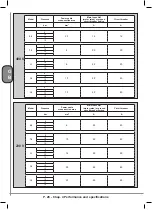
The environmental conditions that represent the operating range of the compressor are indicated below:
- Maximum installation altitude (above sea level) ................................................................................:1000 m
- Minimum ambient temperature .........................................................................................................:+5° C
- Maximum ambient temperature ........................................................................................................:+40° C
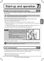
Machine performance, as indicated in this handbook, is guaranteed only if the machine is installed at an
altitude below the operating limit indicated.{228}
Contact the Manufacturer’s Technical Department in the case of particular environmental conditions.
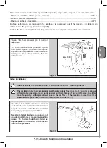
Outdoor installation
Figure 29
shows an example of outdoor
installation.
The compressor must be protected against
atmospheric agents. Suitable protection is
required if the compressor is located outdoors.
Comply with the minimum distance from the
walls (0.6 mm).
Fig. 29
min. 3000
max. 5000
600
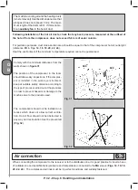
Indoor installation
The machine is not suitable for use in environments with a “risk of explosion”.
The air taken in by the compressor must be absolutely free from dust, vapours, explosive
or flammable gas, solvents or paint powder and toxic fumes of any sort. Replace the filters
more frequently - with special reference to the air filter - if the machine is used in critical
environments (presence of ceramic, marble, cement, dust, etc.).
The dimensions of the installation site and
ventilation devices must ensure that ambient
temperature remains within the limits indicated
during duty cycle operating conditions.
If a suitable hot air discharge opening is not
provided, install one or more air evacuation
hoods. The hoods should be installed as
high as possible in relation to the dimen-
sions of the premises.
Fig. 30
Содержание GENESIS Series
Страница 1: ...GENESIS FORMULA MODULO 5 5 15 kW USE AND MAINTENANCE HANDBOOK GB...
Страница 2: ......
Страница 11: ...IX FORMULA 15 kW BA 69 Fig 17 Fig 18 PC PE SPA CF FA PF CT TRL VR BF PS ES EV FU MA RA RO MP PP VA FO FO VS SS...
Страница 12: ...X MODULO 5 5 7 5 kW Fig 19 Fig 20 FO FD FA SS ES FU MA RA RO PP MP PC PE SCE SF VA EV BF VT TRL CT PF VS PS...
Страница 14: ...XII MODULO 15 kW BA 69 Fig 23 Fig 24 PS PP PF MA FU RA RO ES VA FO FD VS SS MP CF FA SCE PE PC TRL VR BF CT EV...
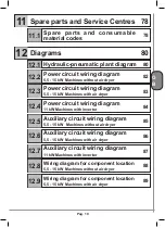
Страница 82: ...P 80 Chap 12 Diagrams G B 12 Diagrams Hydraulic pneumatic plant diagram 12 1...
Страница 84: ...P 82 Chap 12 Diagrams G B Power circuit wiring diagram 5 5 15 kW Machines without air dryer 12 2...
Страница 85: ...P 83 Chap 12 Diagrams G B Power circuit wiring diagram 5 5 15 kW Machines with air dryer 12 3...
Страница 86: ...P 84 Chap 12 Diagrams G B Power circuit wiring diagram 11 kW Machines with inverter 12 4...
Страница 87: ...P 85 Chap 12 Diagrams G B Auxiliary circuit wiring diagram 5 5 15 kW Machines without air dryer 12 5...
Страница 88: ...P 86 Chap 12 Diagrams G B Auxiliary circuit wiring diagram 5 5 15 kW Machines with air dryer 12 6...
Страница 89: ...P 87 Chap 12 Diagrams G B Auxiliary circuit wiring diagram 11 kW Machines with inverter 12 7...
Страница 90: ...P 88 Chap 12 Diagrams G B Wiring diagram for component location 5 5 15 kW Machines without air dryer 12 8...
Страница 91: ...P 89 Chap 12 Diagrams G B Wiring diagram for component location 5 5 15 kW Machines with air dryer 12 9...


