


P. 46 - Chap. 7 Start-up and operation
G
B
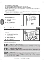
Time to service
Makes it possible to check the first maintenance operation to be carried out on the compressor; the
maintenance operations to be carried out 100 hours after this are also displayed. In this way, the user
can schedule maintenance operations and, if necessary, decide whether to replace several components
during the same maintenance operation
Components life
indicates the remaining service life of each component that requires periodic maintenance
Compon. replacement
If the function is enabled, it makes it possible to reset the component life counters after maintenance
Running hours
Indicates
compressor operating time (total running hours, running hours at full load)
A table with the schedule of the maintenance operations to be carried out is provided below
Intervention
First 100 hours
maintenance
coupon
First 1000 hours
maintenance
coupon
Every 1000 hours Every 2000 hours
Check air filter
•
Replace air filter
•
•
Change oil
•
Replace oil filter
•
•
•
Replace separator
filter
•
Replace air dryer
filters
•
•
Maintenance periods may differ from those indicated.
During installation, Service Centre personnel assess compressor operating conditions and if necessary modify
the frequency of the operations.
7.4.2.3
GENERAL SETTINGS menu
This menu allows to carry out the general settings of compressor operating configuration with the exception
of operating parameters (pressures, timings).
Language
Used to select the language of the messages
Measur. unit
Used to set the measurement units for pressure and temperature
(continued on p
. 49)
Содержание GENESIS Series
Страница 1: ...GENESIS FORMULA MODULO 5 5 15 kW USE AND MAINTENANCE HANDBOOK GB...
Страница 2: ......
Страница 11: ...IX FORMULA 15 kW BA 69 Fig 17 Fig 18 PC PE SPA CF FA PF CT TRL VR BF PS ES EV FU MA RA RO MP PP VA FO FO VS SS...
Страница 12: ...X MODULO 5 5 7 5 kW Fig 19 Fig 20 FO FD FA SS ES FU MA RA RO PP MP PC PE SCE SF VA EV BF VT TRL CT PF VS PS...
Страница 14: ...XII MODULO 15 kW BA 69 Fig 23 Fig 24 PS PP PF MA FU RA RO ES VA FO FD VS SS MP CF FA SCE PE PC TRL VR BF CT EV...
Страница 82: ...P 80 Chap 12 Diagrams G B 12 Diagrams Hydraulic pneumatic plant diagram 12 1...
Страница 84: ...P 82 Chap 12 Diagrams G B Power circuit wiring diagram 5 5 15 kW Machines without air dryer 12 2...
Страница 85: ...P 83 Chap 12 Diagrams G B Power circuit wiring diagram 5 5 15 kW Machines with air dryer 12 3...
Страница 86: ...P 84 Chap 12 Diagrams G B Power circuit wiring diagram 11 kW Machines with inverter 12 4...
Страница 87: ...P 85 Chap 12 Diagrams G B Auxiliary circuit wiring diagram 5 5 15 kW Machines without air dryer 12 5...
Страница 88: ...P 86 Chap 12 Diagrams G B Auxiliary circuit wiring diagram 5 5 15 kW Machines with air dryer 12 6...
Страница 89: ...P 87 Chap 12 Diagrams G B Auxiliary circuit wiring diagram 11 kW Machines with inverter 12 7...
Страница 90: ...P 88 Chap 12 Diagrams G B Wiring diagram for component location 5 5 15 kW Machines without air dryer 12 8...
Страница 91: ...P 89 Chap 12 Diagrams G B Wiring diagram for component location 5 5 15 kW Machines with air dryer 12 9...


