


P. 62 - Chap 5 Troubleshooting
9
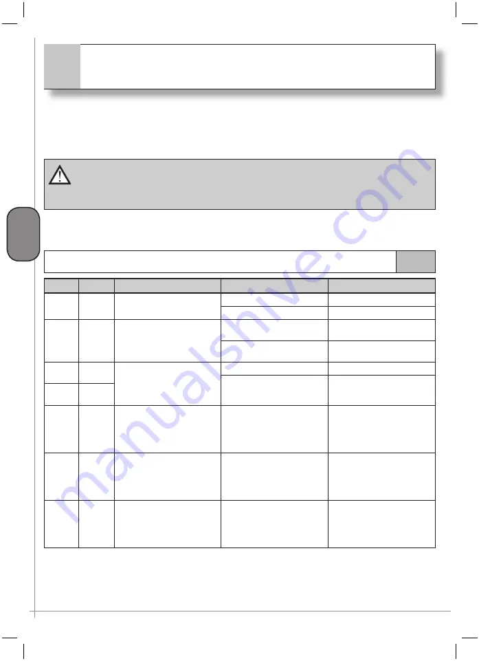
Troubleshooting
G
B
The following table shows the most frequent problems.
The operation should be carried out by a qualifi ed and skilled person where shown. For all other cases,
contact a specialised Centre
When the compressor requires scheduled maintenance, the operation to be performed and
the number of excess hours of operation are indicated in the main screen page.
In the case of long-term functioning in these conditions, the compressor is blocked and the
operation must be carried out immediately
V-F
Fixed speed compressors
V.V.
Variable speed compressors
9.1
The machine does not start
V-F
V-V
Indication
Possible cause
Intervento
X
X
L1
OFF
DI
OFF
No
power
Restore power
FU2
/
FU8
blown
Replace damaged fuses
X
X
L1
ON
DI
OFF
Problems in the electronic
control unit
Call
Customer
Service Centre
Problems in control unit
connections
Call
Customer
Service Centre
X
X
L1
ON
DI
ON
(with normal functioning
message)
FU4
blown
Replace
FU4
Inverter
problems
Call
Customer
Service Centre
X
X
X
L1
ON
L3
constant ON
DI
indicates:
“Ambient temperature too
low - block”
Ambient temperature
too low
Heat ambient.
Check installation
requirements
X
X
L1
ON
L3
constant ON
DI
indicates:
“Press. Transducer
error - block”
Problems in the
pressure
sensor
or in its electrical
connections
Call
Customer
Service Centre
X
X
L1
ON
L3
constant ON
DI
indicates:
“Temperature sensor
error - block”
Problems in the
temperature
sensor
or in its electrical
connections
Call
Customer
Service Centre
Содержание GENESIS Series
Страница 1: ...GENESIS FORMULA MODULO 5 5 15 kW USE AND MAINTENANCE HANDBOOK GB...
Страница 2: ......
Страница 11: ...IX FORMULA 15 kW BA 69 Fig 17 Fig 18 PC PE SPA CF FA PF CT TRL VR BF PS ES EV FU MA RA RO MP PP VA FO FO VS SS...
Страница 12: ...X MODULO 5 5 7 5 kW Fig 19 Fig 20 FO FD FA SS ES FU MA RA RO PP MP PC PE SCE SF VA EV BF VT TRL CT PF VS PS...
Страница 14: ...XII MODULO 15 kW BA 69 Fig 23 Fig 24 PS PP PF MA FU RA RO ES VA FO FD VS SS MP CF FA SCE PE PC TRL VR BF CT EV...
Страница 82: ...P 80 Chap 12 Diagrams G B 12 Diagrams Hydraulic pneumatic plant diagram 12 1...
Страница 84: ...P 82 Chap 12 Diagrams G B Power circuit wiring diagram 5 5 15 kW Machines without air dryer 12 2...
Страница 85: ...P 83 Chap 12 Diagrams G B Power circuit wiring diagram 5 5 15 kW Machines with air dryer 12 3...
Страница 86: ...P 84 Chap 12 Diagrams G B Power circuit wiring diagram 11 kW Machines with inverter 12 4...
Страница 87: ...P 85 Chap 12 Diagrams G B Auxiliary circuit wiring diagram 5 5 15 kW Machines without air dryer 12 5...
Страница 88: ...P 86 Chap 12 Diagrams G B Auxiliary circuit wiring diagram 5 5 15 kW Machines with air dryer 12 6...
Страница 89: ...P 87 Chap 12 Diagrams G B Auxiliary circuit wiring diagram 11 kW Machines with inverter 12 7...
Страница 90: ...P 88 Chap 12 Diagrams G B Wiring diagram for component location 5 5 15 kW Machines without air dryer 12 8...
Страница 91: ...P 89 Chap 12 Diagrams G B Wiring diagram for component location 5 5 15 kW Machines with air dryer 12 9...


