Manuale di installazione, Uso e Manutenzione -
Installation, Use and Maintenance Manual
pag. 15
7.7
COLLEGAMENTI IDRAULICI
• Le operazioni di installazione e collegamento delle tubazioni idrauliche
sono operazioni che possono compromettere il buon funzionamento
dell'impianto o, peggio, causare danni irreversibili alla macchina. Queste
operazioni sono da effettuarsi
solo da personale specializzato.
7.7 H
YDRAULIC CONNECTIONS
• The installation and connection operations of the hydraulic pipes are
operations that can compromise the good functioning of the plant or
worse, cause irreversible damage to the machine. These operations
must
only be performed by specialised staff.
• I canali devono essere dimensionati a funzione dell’impianto e delle carat-
teristiche aerauliche dei ventilatori dell’unità. Un errato calcolo delle cana-
lizzazioni causa perdite di potenza o l’intervento di eventuali dispositivi pre-
senti sull’impianto.
• Per prevenire la formazione di condensa ed attenuare il livello di rumorosi-
tà si consiglia di utilizzare canali coibentati.
• Per evitare di trasmettere le eventuali vibrazioni della macchina in
ambiente, è consigliato interporre un giunto antivibrante fra le bocche
ventilanti e i canali. Deve comunque essere garantita la continuità elettri-
ca fra canale e macchina tramite un cavo di terra.
• The ducts must be dimensioned depending on the plant and the aerau-
lic features of the unit fans. An incorrect calculation of the ducting cau-
ses a loss of power or the intervention of any devices present on the
plant.
• It is recommended to use insulated ducts to prevent the formation of
condensate and attenuate the noise level.
• To prevent transmission of any machine vibrations into the environment
it is recommended top lace an anti-vibration joint between the fan
vents and the ducts. The electrical continuity must however be gua-
ranteed between the duct and the machine via the earth cable.
7.5 P
OSIZIONAMENTO DELLA MACCHINA
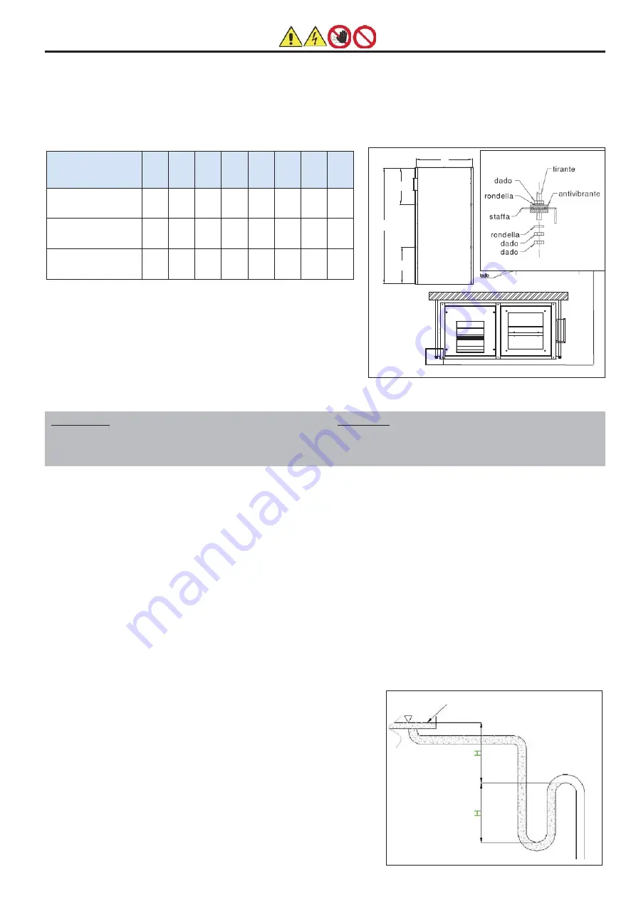
Qui di seguito sono illustrate alcune sequenze del montaggio:
1. Eseguire la foratura a soffitto e fissare i tiranti filettati M8 come indicato
in figura.
2. Posizionare l'unità sui tiranti
3. Bloccare l'unità serrando i bulloni di fissaggio.
7.5 P
OSITIONING OF THE MACHINE
Some assembly sequences are illustrated below:
1. Drill the ceiling and fix M8 threaded tie-rods, as indicated in the figure.
2. Position the unit on the tie-rods
3. Block the unit by fastening the fixing bolt
IMPORTANTE: SI FA DIVIETO DI METTERE IN FUNZIONE
L'UNITÀ SE LE BOCCHE DEI VENTILATORI NON SONO CANA-
LIZZATE O PROTETTE CON RETE ANTINFORTUNISTICA
SECONDO LE NORMATIVE VIGENTI.
IMPORTANT: IT IS PROHIBITED TO START THE UNIT IF THE
FAN VENTS ARE NOT DUCTED OR PROTECTED WITH ACCI-
DENT-PREVENTION MESH ACCORDING TO THE CURRENT
REGULATION.
allo scopo di favorire il regolare deflus-
so della condensa si consiglia di monta-
re la macchina inclinata di 3 mm verso
lo scarico condensa.
with the purpose of favouring the
regular flow of condensate, it is
advised to mount the machine incli-
ned by 3 mm towards the conden-
sate drain.
7.7.1 Collegamento scarico condensa
• Le unità della serie CFR+/CFRE+ sono
tutte dotate di vasca raccogli condensa in
lamiera zincata.
• La vasca di raccolta condensa è provvista
di raccordo di scarico Ø 21 mm.
• Il sistema di scarico deve prevedere un ade-
guato sifone per prevenire l'indesi derata
entrata d'aria nei sistemi in depressione o l'in-
desiderata uscita d'aria nei sistemi in pres-
sione. Tale sifone risulta inoltre utile per evi-
tare l'infiltrarsi di odori o insetti.
• Il dimensionamento e l'esecuzione dei sifo-
ni nel caso di vasca in depressione (o in
pressione) deve garantire che H>P, dove P
espresso in mm.c.a., è pari alla pressione
statica utile della macchina installata (figura
a lato).
7.7.1 Condensate drain connection
• The CFR+/CFRE+ range units are all
equipped with condensate drip tray made
of galvanized metal sheet.
• The condensate drip tray has a drain with Ø
21 mm.
• The drain system must have a suitable
siphon for preventing the undesired entry of
air into the depressurised systems or the
undesired exit of air in pressurised systems.
This siphon is also useful to prevent the infil-
tration of odours or insects.
• The dimensioning and the version of the
siphons in the casve of the depressurised
tray (or pressurised) must guarantee that
H>P, where P expressed in mm.w.c. is
equal to the useful static pressure of the
machine installed (figure at the side).
Livello vasca condensa
Drip tray level
A
C
C
B
Modello
/ Model
CFR+
CFRE+
40 N 75 N 100 N 150 N 200 N 320 N 400 N 500 N
A (mm)
1445 1905 1905 2165 2165 2465 2465 2465
B (mm)
855 1045 1045 1055 1455 1455 1455 1755
C (mm)
/
593
593
682
682
762
762
762
7.6 C
OLLEGAMENTO AI CANALI
7.6 C
ONNECTION TO THE DUCTS
7 - INSTALLAZIONE E MESSA IN SERVIZIO
7 - INSTALLATION AND START UP


