


Illustration:
1. Blue probe short connected to water outlet pipe.
2. Red probe connected to upper head cover.
3. Black probe connected to middle head cover.
4. White probe connected to lower head cover.
Circuit Diagram
COM
COM
COM
NO
NO
NO
N
N
KA1
KA3
KA4
EH1
EH2
L1
L
Ten-core Cable
Control Board
Black wire
3kW Heating Element
(Upper side of the tank)
2kW Heating Element
(Lower side of the tank)
White wire
L
N PE
Temperature Sensor
To Water Tank
Yellow/Green wire
Yellow wire
Black wire
Red wire
Power Board
Thermal Cutout
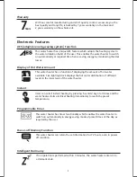
15
Quick
Standard
Heat
Modes
MAX
kWh
Hot Water
Quantity
Override
Energy
meter
Timer3
0
C
:
8888
Timer 2
Timer 1
Timer 3
MAX
Low
Timer ON
Timer OFF
0
C
Clock/
Timers
Содержание HSE-HNS
Страница 23: ......