149
User Manual ENGLISH
WHG-Series Wireless WLAN Controller
Copyright © 2017, 4ipnet, Inc. All rights reserved. All other trademarks mentioned are the property of their respective owners.
Appendix A. Hardware Overview
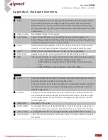
WHG201
1 Reset
Press and hold for over 3 seconds and status of LED on front panel will start to
blink, release button at this stage to restart the system. Press and hold the
Reset button for more than 10 seconds and status of LED on the front panel
will turn from blinking to off, release at this stage to reset the system to default
configuration.
2 Power button
Main ON/OFF power of the system.
3 LED Displays
Power: Power LED lights up as constant green when power supply is on.
Status: Blinking indicates that the system OS is booting up. When the system is
ready for operation, the LED is lit up constantly.
4 Port1
WAN port (10/100/1000 Base-T RJ-45) for uplink connections to the external
network, such as the ADSL Router from your ISP (Internet Service Provider).
5 Port2
WAN2 or LAN1 (10/100/1000 Base-T RJ-45) function configurable.
6 Port3-Port5
Gigabit LAN ports for servicing LAN traffic (10/100/1000 Base-T RJ-45)
7 USB
USB console interface. The cable should be the combination of below 3 cables
-
1 Port USB to RS232 DB9 Serial Adapter Cable - M/M
-
RS232 DB9 Serial Adapter Cable to RS232 DB9 Serial Adapter Cable -
F/F
-
RS232 DB9 Serial Adapter Cable to 1 Port USB - M/M
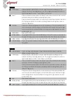
WHG321
1 Reset
Press and hold the Reset button for about 5 seconds and status of LED on front
panel will start to blink before restarting the system.
Press and hold the Reset button for more than 10 seconds and status of LED on
the front panel will start to speed up blinking before resetting the system to
default configuration.
2 Console
The system can be configured via a serial console port. The administrator can
use a terminal emulation program such as Microsoft’s Hyper Terminal to login
to the configuration console interface to change admin password or monitor
system status, etc.
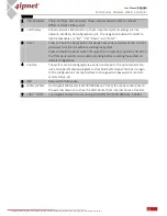
3 USB1/USB2
Reserved for future use.
4 WAN1/WAN2
Dual Gigabit WAN ports (10/100/1000 Base-T RJ-45) for uplink connections to
the external network, such as the ADSL Router from Internet Service Provider.
5 LAN1 ~ LAN2
Two Gigabit LAN ports for servicing LAN traffic (10/100/1000 Base-T RJ-45).
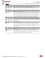
6 LED Indicators
There are two LED indicators, Power and Status, to indicate different status of
the system.


