PAGE 54
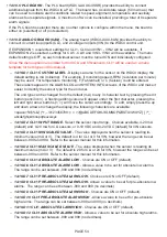
• 14.10.C PLC BOARD
- The PLC board (WDC4-AUXO-4SSR) provides the ability to connect
additional signals from the WDC4 to a PLC. The board has 4 solid state relays (50 mA max.) that
can be used to indicate alarm conditions related to speed, alignment, temperature and auxiliary
alarms as four separate signals. A maximum of two can be installed, providing a total of 8 separate
alarm signals.
If the PLC board is selected there are no other options to configure within the menu, the board is
either on (selected) or off (not selected).
• 14.10.D ANALOG BOARD (6AN)
- The analog board (WDC4-AUXI-6AN) provides the ability to
connect 4 current loop inputs (CLI), and 2 voltage in inputs (VIN) to the WDC4 control unit.
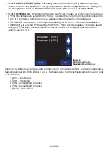
If EXPANSION 1 is selected, settings for CLI1 - CLI4 and VIN1 - VIN2 will be available. If
EXPANSION 2 is selected, settings for CLI5 - CLI8 and VIN3 - VIN4 will be available. The menu
default setting is OFF, so each individual sensor must be turned ON and individually configured.
Since the menu options are similar for both CLI and VIN sensors, CLI1 will be used as a menu
template for both types in this manual.
–
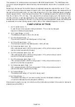
14.10.D.1 CLI1: CUSTOM LABEL
- Displays a name for the sensor on the WDC4 display, the
default setting is mA (milliamp). For example, if monitoring speed, RPM (revolution per minute)
may be used. For temperature monitoring, F (Fahrenheit) or C (Celsius) could be entered.
These labels appear in the ALARM LOG and SYSTEM INFO screens of the WDC4 and make it
easier to identify the sensor type for the end user.
The unit type can be changed from the default (mA) to any 3 character text by pressing the edit
button (pencil icon). A flashing editing cursor will appear under the first character, pressing the
left and right arrow buttons (< >) will move the cursor accordingly. To edit, simply press the up
and down arrows to change the display, the following characters are available:
<space>!”#$%&’( )*+,-./0123456789:;< = >?@ABCDEFGHIJKLMNOPQRSTUVWXYZ[ ] /^_’
abcdefghijklmnopqrtsuvwxyz
–
14.10.D.2 CLI1: INPUT RANGE
- Select the sensor input range. Choices available, 4-20 mA
(default) and 0-20 mA for CLI sensors, or 0-10 VDC and 0-24 VDC (default) for VIN sensors.
–
14.10.D.3 CLI1: MIN SCALED VALUE
- The value displayed when the sensor is reading its
minimum value (mA or V). The default is 4 for CLI or 0 for VIN, however the range can be set
between -999 and 999. Refer to the sensor manual for this information.
–
14.10.D.4 CLI1: MAX SCALED VALUE
- The value displayed when the sensor is reading its
maximum value (mA or V). The default is 20 for CLI or 24 for VIN, however the range can be set
between -999 and 999. Refer to the sensor manual for this information.
–
14.10.D.5 CLI1: ABSOLUTE ALARM LOW
- Choices are ON or OFF (default).
–
14.10.D.6 CLI1: ABSOLUTE ALARM LOW
- Allows a value to be set for absolute low alarms.
The range can be set between -999 and 999 (no decimals).
–
14.10.D.7 CLI1: PRE-ABSOLUTE ALARM LOW
- Choices are ON or OFF (default).
–
14.10.D.8 CLI1: PRE-ABSOLUTE ALARM LOW
- Allows a value to be set for pre-absolute low
alarms. The range can be set between -999 and 999 (no decimals).
–
14.10.D.9 CLI1: PRE-ABSOLUTE ALARM HIGH
- Choices are ON or OFF (default).
–
14.10.D.10 CLI1: PRE-ABSOLUTE ALARM HIGH
- Allows a value to be set for pre-absolute
high alarms. The range can be set between -999 and 999 (no decimals).
–
14.10.D.11 CLI1: ABSOLUTE ALARM HIGH
- Choices are ON or OFF (default).
–
14.10.D.12 CLI1: ABSOLUTE ALARM HIGH
- Allows a value to be set for absolute high alarms.
The range can be set between -999 and 999 (no decimals).
Содержание Watchdog Super Elite
Страница 72: ...PAGE 72 END USER NOTES...
Страница 73: ...PAGE 73 END USER NOTES...
Страница 74: ...PAGE 74 PAGE 74 END USER NOTES...


