PAGE 11
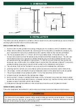
5. DIMENSIONS
ALL DIMENSIONS IN INCHES
6
9-1/2
3-1/2
Ø 1-1/8 x 2
Ø 5/16 x 4
10-7/8
11-3/4
5-1/4
WARNING
The Control Unit is susceptible to static voltage, static handling precautions should be taken. Connection
of a clean ground to terminal 16 is essential for optimum performance. Since the enclosure is a static
hazard, it should only be cleaned with a damp cloth.
6. INSTALLATION
The WDC4 should be installed in a suitable control or switch room, and mounted at eye level so that the
warning lights and LED screen can be readily seen.
ENCLOSURE INSTALLATION -
1.
Use the correct cable, glands and sealing arrangement in accordance with all installation codes.
2.
Where other certified components are used as part of the assembly or installation procedure, the
user must take into account any limitations which might be listed on the relevant certificates.
3.
The box is supplied with 2 x 1-1/8 inch (28.5 mm) pre drilled holes in the bottom face. All
unused entry apertures must be sealed using component certified stopping plugs. The end user
must install component or apparatus certified stopping plugs and cable glands/conduit in strict
accordance with the manufacturer’s instructions. In order to connect conduit to the control unit
enclosure, use a CSA and/or UL certified Class II conduit hub (for example, a Myers™ hub) with a
suitable bonding (grounding) connection that is rated for the installation environment.
4.
The enclosure must not be modified in any way, as this will invalidate the certification.
5.
All wiring must be carried out in accordance with relevant codes of practice and/or instructions.
6.
The voltage, current and maximum power dissipation shown on the label must not be exceeded.
7.
The wiring installation must extend to within 1 mm of the metal face of the terminal.
8.
All leads must be insulated for the appropriate voltage.
9.
Not more than 1 single or multiple strand cable is to be connected to any terminal unless multiple
conductors have previously been joined in a suitable manner (e.g. boot lace ferrule) such that they
present a single connection point to the terminal.
10.
A flat-head or straight screwdriver of the correct size should be used to tighten terminals.
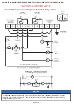
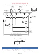
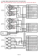
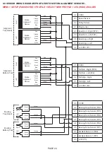
SENSOR INSTALLATION -
Follow the installation instructions for each sensor as provided in each individual product manual.
Содержание Watchdog Super Elite
Страница 72: ...PAGE 72 END USER NOTES...
Страница 73: ...PAGE 73 END USER NOTES...
Страница 74: ...PAGE 74 PAGE 74 END USER NOTES...


