PAGE 18
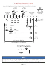
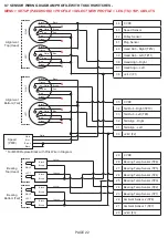
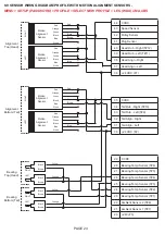
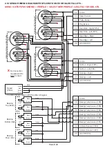
9.4 CONTROL WIRING DIAGRAM FOR MULTIPLE UNITS WIRED TO THE SAME ALARM -
6
7
8
9
10
11
12
13
14
15
16
N/C
N/O
COM
N/C
N/O
COM
100 to 240 VAC
Interlock
(Run Signal)
120 to 240 VAC
Watchdog
Supply
The Unit Must
be Grounded
Watchdog
Alarm Relay
Watchdog
Stop Relay
Fuse
2 Amp
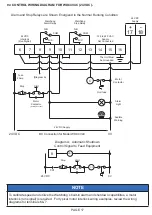
(Diagram A)
C
Overload
Motor
Contactor
Alarm
Light
External
Relay #1
(Diagram B)
Start
Stop
Motor
Contactor
(Holding Contact)
L
N
AC Connection for Model WDC4V46C
120 to 240 VAC ± 50/60 Hz Supply
R1
WATCHDOG CONTROL UNIT #1
Alarm and Stop Relays are Shown Energized in the Normal Running Condition
Start
Stop
C1
C1
CR1
8
N
L
CR1
Diagram A: Automatic Shutdown
Control Signal to Feed Equipment
+
17
-
18
24 VDC
Supply
No Connection
NOTE
To calibrate speed and utilize the Watchdog’s built-in alarm and shutdown capabilities, a motor
interlock (run signal) is required. For typical motor interlock wiring examples, review the wiring
diagrams for terminals 6 & 7.
Содержание Watchdog Super Elite
Страница 72: ...PAGE 72 END USER NOTES...
Страница 73: ...PAGE 73 END USER NOTES...
Страница 74: ...PAGE 74 PAGE 74 END USER NOTES...


