3xLogic VX-2M-D2-RIA Скачать руководство пользователя страница 14

VISIX S-Series Network Camera 

|


USER MANUAL v6.0 


10385 Westmoor Drive, Suite 210, Westminster, CO 80021 | www.3xlogic.com | (877) 3XLOGIC


14 


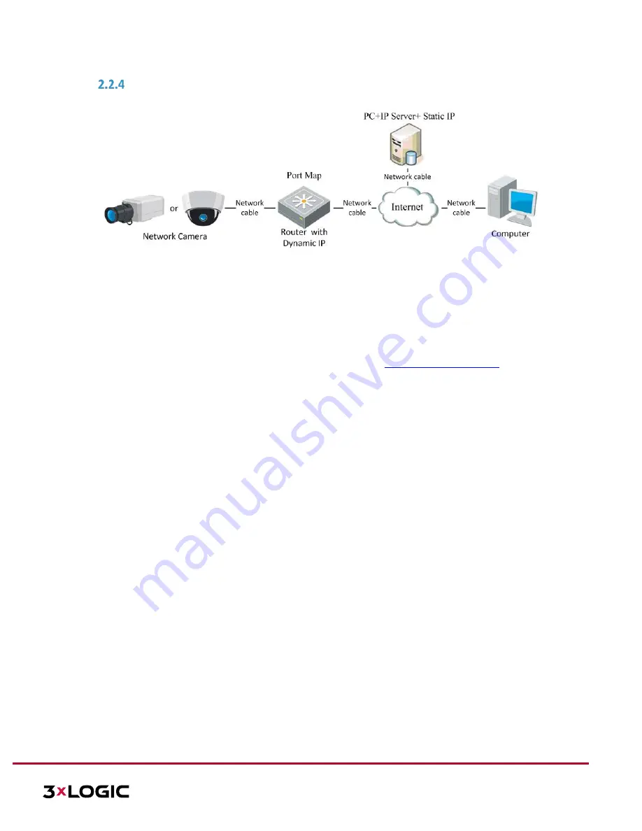
PRIVATE DOMAIN NAME RESOLUTION 


Figure 2-9


Private Domain Name Resolution 

Steps: 

1).


Install and run the IP Server software in a computer with a static IP. 

2).


Access the network camera through the LAN with a web browser or the client software. 

3).


Enable DDNS and select IP Server as the protocol type. Refer to 

Configuring DDNS Settings

 for detailed 

configuration. 


Содержание VX-2M-D2-RIA

Страница 1: ...VISIX S Series Network Camera USER MANUAL v6 0 10385 Westmoor Drive Suite 210 Westminster CO 80021 www 3xlogic com 877 3XLOGIC 1 VISIX S Series Network Camera User Manual V6 0 ...

Страница 2: ...atures being added in firmware versions released after the discontinuation of the VISIX line Please contact your 3xLOGIC support representative for more info Thank you for purchasing our product If there are any questions or requests please do not hesitate to contact the dealer NOTE This manual may contain technical inaccuracies or printing errors The content is subject to change without notice Th...

Страница 3: ...ference This device must accept any interference received including interference that may cause undesired operation EU Conformity Statement This product and if applicable the supplied accessories too are marked with CE and comply therefore with the applicable harmonized European standards listed under the Low Voltage Directive 2006 95 EC the EMC Directive 2004 108 EC the RoHS Directive 2011 65 EU ...

Страница 4: ...AC depending on models according to the IEC60950 1 and Limited Power Source standard If the product does not work properly please contact your dealer or the nearest service center Never attempt to disassemble the camera yourself We shall not assume any responsibility for problems caused by unauthorized repair or maintenance To reduce the risk of fire or electrical shock do not expose this product ...

Страница 5: ...nvironment and do not expose it to high electromagnetic radiation To avoid heat accumulation good ventilation is required for a proper operating environment Keep the camera away from water and any liquid While shipping the camera should be packed in its original packing Improper use or replacement of the battery may result in hazard of explosion Please use the manufacturer recommended battery type...

Страница 6: ... ADDING A VISIX S SERIES CAMERA TO VIGIL SERVER 15 3 2 ACCESS UI VIA WEB BROWSER 17 4 BASIC OPERATION 19 4 1 CONFIGURING LOCAL PARAMETERS 19 4 2 LIVE VIEW 20 Live view page COMPONENT DESCRIPTIONS 20 4 3 RECORDING AND CAPTURING PICTURES MANUALLY 21 4 4 OPERATING PTZ CONTROL 21 PTZ Control Panel 22 Setting a Preset 23 Calling a Preset 23 Setting Calling a Patrol 24 Setting Calling a Pattern 25 4 5 P...

Страница 7: ...tial Position 54 Configuring Park Actions 54 Configuring Privacy Mask 55 Configuring Scheduled Tasks 56 Clearing PTZ Configurations 57 Configuring Smart Tracking 57 Prioritize PTZ 58 Position Settings 58 6 CAMERA CONFIGURATION 60 6 1 CONFIGURING NETWORK SETTINGS 60 Basic Settings 60 Advanced Settings 64 6 2 CONFIGURING VIDEO AND AUDIO SETTINGS 71 Configuring Video Settings 71 Configuring Audio Set...

Страница 8: ...Operating System Microsoft Windows XP SP1 and above version Vista Win7 Server 2003 Server 2008 32bits CPU Intel Pentium IV 3 0 GHz or higher RAM 1G or higher Display 1024 768 resolution or higher Web Browser Internet Explorer 6 0 and above version Safari 5 02 and above version Mozilla Firefox 3 5 and above version and Google Chrome8 and above versions ...

Страница 9: ... LAN To view and configure the camera via a LAN you need to connect the network camera in the same subnet with your computer and install the 3xLOGIC VISIX detection software This will allow you to search and change the IP address of the detected network cameras WIRING OVER THE LAN The following figures show the two methods of cable connection between a network camera and a computer To test the net...

Страница 10: ...ce version etc is recommended An example is shown in Figure 2 3 This utility is installed alongside VIGIL Server or can be downloaded separately If on a VIGIL Server system launch utility from Start Programs VIGIL Utility or download the utility from the 3xLOGIC website s Software Support Center VIGIL Utilities http www 3xlogic com software center to a Windows PC Steps 1 Launch the utility 2 Click...

Страница 11: ...sic Settings Configuring TCP IP Settings 2 2 Setting the Network Camera over the WAN This section explains how to connect the network camera to the WAN with a static IP or a dynamic IP STATIC IP CONNECTION Before you start Please apply a static IP from an ISP Internet Service Provider With the static IP address you can connect the network camera via a router or connect it to the WAN directly Conne...

Страница 12: ...ynamic IP from an ISP With the dynamic IP address you can connect the network camera to a modem or a router Connecting the network camera via a router Steps 1 Connect the network camera to the router 2 In the camera assign a LAN IP address the subnet mask and the gateway Refer to Detecting and Changing the IP Address for detailed LAN configuration 3 In the router set the PPPoE user name password a...

Страница 13: ...Dynamic IP NOTE The obtained IP address is dynamically assigned via PPPoE so the IP address always changes after rebooting the camera To solve the inconvenience of the dynamic IP you need to get a domain name from the DDNS provider E g DynDns com Please follow the steps below for normal domain name resolution and private domain name resolution to solve the problem NORMAL DOMAIN NAME RESOLUTION Fig...

Страница 14: ...AIN NAME RESOLUTION Figure 2 9 Private Domain Name Resolution Steps 1 Install and run the IP Server software in a computer with a static IP 2 Access the network camera through the LAN with a web browser or the client software 3 Enable DDNS and select IP Server as the protocol type Refer to Configuring DDNS Settings for detailed configuration ...

Страница 15: ...k Camera checkbox The Network Camera Settings form will deploy If the form does not deploy automatically click the Network Camera Settings button 5 Click the Detect Cameras button located next to the Type field The 3xLOGIC Camera Setup Utility will deploy and will automatically begin detecting devices on the network Figure 3 1 Launching the 3xLOGIC Camera Setup Utility 6 Select the desired camera ...

Страница 16: ...a Settings form then click Apply on the VIGIL Server Settings window to save the new settings The camera will now be saved to VIGIL and can be accessed and controlled via the VIGIL Server UI Any other applicable VIGIL utilities VIGIL Client View Lite II that have been interfaced with the VIGIL Server will also be able to access and control the camera See the VIGIL Server and VIGIL Client User Guid...

Страница 17: ...en configured during camera activation If the camera has already been configured using one of 3xLOGIC s setup tools VIGIL Easy Setup Wizard 3xLOGIc Camera Setup Utility then default credentials will have been changed by the installer this is a standard security precaution enforced by the setup tools Contact your security network administrator for credentials NOTE English is the only supported lang...

Страница 18: ...s Network Camera USER MANUAL v6 0 10385 Westmoor Drive Suite 210 Westminster CO 80021 www 3xlogic com 877 3XLOGIC 18 Figure 3 5 Download and Install Plug in Figure 3 6 Install Plug in 1 Figure 3 7 Install Plug in 2 ...

Страница 19: ...audio and video streams though video quality may be lowered due to bandwidth limitations HTTP Allows the same quality as TCP without setting specific ports for streaming under some network environments MULTICAST It s recommended to select MCAST type when using the Multicast function For detailed information about Multicast refer to Section 9 1 Configuring Basic Settings Configuring TCP IP Settings...

Страница 20: ... directory for saving the clips and pictures and click Open to select the desired folder 3 Click Save to save the settings 4 2 Live View The live view page allows you to view the real time video capture images utilize PTZ control set call presets and configure video parameters Log in the network camera to enter the live view page or you can click Live View on the menu bar of the main page to enter...

Страница 21: ... the web browser Manually take a stillshot Manually start stop recording Audio on and adjust volume Mute Engage two way audio multiple channels available on applicable devices Turn on off digital zooming function Table 5 1 Live View Toolbar Descriptions 4 3 Recording and Capturing Pictures Manually In the live view interface click on the toolbar to capture live stillshots or click to manually trig...

Страница 22: ...rol Panel 7 Click the zoom iris focus buttons to utilize lens control There are 8 direction arrows in the live view window when you click and drag the mouse in the relative positions For cameras which support lens movement only the direction buttons are invalid Icon Description Zoom in out Focus near far Iris Light on off Wiper on off One touch focus Initialize lens Adjust speed of pan tilt moveme...

Страница 23: ...r can configure up to 128 presets CALLING A PRESET This feature enables the camera to point to a specified preset scene manually or when an event takes place A user can call a preset at any time to shift position to the desired preset coordinates In the PTZ control panel select a defined preset from the list and click to call the preset Alternatively select the Presets interface and call the prese...

Страница 24: ...ilt scan 42 Call pattern 2 101 Start panorama scan 43 Call pattern 3 102 Call patrol 5 44 Call pattern 4 103 Call patrol 6 45 One touch Patrol 104 Call patrol 7 90 Wiper 105 Call patrol 8 Figure 4 7 Special Preset NOTE You may need to use the OSD On Screen Display menu when controlling the camera remotely To display the OSD menu on the live view screen you can call the preset number 95 SETTING CAL...

Страница 25: ... camera models Setting a Pattern Steps 1 In the PTZ control panel click to enter the pattern settings interface 2 Select a pattern number from the list as shown in Figure 4 9 Figure 4 9 Patterns Settings Interface 3 Click to enable recording the panning tilting and zooming actions 4 Use the PTZ control buttons to move the lens to the desired position after the information of PROGRAM PATTERN REMAIN...

Страница 26: ...elete the selected preset patrol pattern Start recording a pattern Stop recording the pattern NOTE These 4 patterns can be operated separately and with no priority level When configuring and calling the pattern proportional pan is valid the limit stops and auto flip will be invalid and the 3D positioning operation is not supported ...

Страница 27: ...er interface Note Playback footage can also be retrieved via VIGIL Client and other VIGIL VMS clients that have been properly interfaced with the camera Steps 12 Click Playback on the menu bar to enter the playback interface Figure 4 10 Playback Interface 13 Select the date and click Search Figure 4 11 Search Video 14 Click to play the video files found on this date The toolbar on the bottom of Pl...

Страница 28: ...buttons NOTE The user can choose the local file paths for downloaded playback files and snapshots pictures via the Local Configuration interface Please refer to Section 4 1 Local Configuration for details Drag the progress bar with the mouse to locate your desired playback point The user can also input the time in the Set playback time field and click to locate the playback point Click to zoom out...

Страница 29: ...ure search Make sure the capture schedule is configured Go to Configuration Storage Schedule Settings Capture to set the capture schedule Figure 4 16 Picture Search Interface Steps 1 Select the file type from the dropdown list Continuous Motion Alarm Motion Alarm Motion Alarm Line Crossing Intrusion Detection and Scene Change Detection are selectable 2 Select the start time and end time 3 Click Se...

Страница 30: ...recorded via scheduled recording are stored in the memory card if supported or on the network disk If interfaced with a VIGIL Server recorded files will be stored in the VIGIL Server s media drive Steps 1 Enter the Record Schedule settings interface Configuration Storage Schedule Settings Record Schedule Figure 5 1 Recording Schedule Interface 2 Toggle the Enable checkbox to enable scheduled recor...

Страница 31: ...od of Motion Detection settings interface For detailed information refer to Motion Detection Record Triggered by Alarm If you select Alarm the video will be recorded when the alarm is triggered via the external alarm input channels Besides configuring the recording schedule you have to set the Alarm Type and toggle Trigger Channel checkbox in the Linkage Method of Alarm Input settings interface Fo...

Страница 32: ... enter the Capture Parameters interface 8 Toggle the Enable Timing Snapshot checkbox to enable continuous snapshots and configure the schedule for this mode accordingly Toggle the Enable Event triggered Snapshot checkbox to enable event triggered snapshot 9 Select the format resolution and quality of the snapshot 10 Set the time interval between two snapshots 11 Click to save the settings Uploadin...

Страница 33: ...e file path of the network disk 3 Select the mounting type NFS and SMB CIFS are selectable The user can set the user name and password to guarantee security if SMB CIFS is selected NOTE Refer to the NAS User Manual for creating the file path Warning For your privacy and to better protect your system against security risks we strongly recommend the use of strong passwords for all functions and netw...

Страница 34: ...the disk 3 When the initialization completes the status of disk will become Normal as shown in Figure 5 7 Figure 5 7 View Disk Status Define the Quota for Record and Pictures 1 Input the quota percentage for pictures stillshots and for recording 2 Click Save and refresh the browser page to activate the settings Figure 5 8 Quota Settings NOTE Up to 8 NAS disks can be connected to the camera To init...

Страница 35: ...e functions vary depending on different camera models CONFIGURING MOTION DETECTION Purpose Motion detection detects object movement in the configured surveillance area and a series of actions can be taken when the alarm is triggered In order to detect the moving objects accurately and reduce the false alarm rate normal configuration and expert configuration are selectable for different motion dete...

Страница 36: ...ogic com 877 3XLOGIC 36 Figure 5 9 Motion Detection Settings Normal Steps 1 Click and drag the mouse on the live video image to draw a motion detection area 2 Click to finish drawing NOTE The user can click to clear all motion areas 3 Move the slider to set the sensitivity of the detection mechanism Expert ...

Страница 37: ...y and night mode according to illumination automatically 4 Scheduled Switch Switch to the day night mode according to the configured time You need to set the start time and end time 5 Select Area from the dropdown list to configure 6 Set the sensitivity and percentage values 7 Sensitivity The greater the value is the easier the alarm will be triggered 8 Percentage When the proportional size of the...

Страница 38: ...d end time of the arming task 3 After you set the scheduled task you can click and copy the task to other days optional Figure 5 12 Arming Time Schedule 4 After setting the arming schedule you can click a segment to display the segment arming settings interface to edit the segment record parameters optional Figure 5 13 Segment Arming Settings 5 Click to save settings NOTE The time of each period c...

Страница 39: ... exception or alarm signal to remote management software when an event occurs Send Email Send an email with alarm information to a user or users when an event occurs NOTE To send an Email when an event occurs you need to refer to Configuring Email Settings to set the Email parameters Upload to FTP Memory NAS Capture the image when an alarm is triggered and upload the picture to an FTP server NOTE ...

Страница 40: ...Tampering Figure 5 15 Tampering Alarm 2 Check Enable checkbox to enable the tampering detection 3 Click tab to enter the arming schedule settings interface The arming schedule configuration is identical to configuring the arming schedule for motion detection Refer to Section 5 2 1 Configuring Motion Detection 4 Click tab to select the linkage method taken for tampering Notify Surveillance Center S...

Страница 41: ... 1 Configuring Motion Detection for more details 4 Click the tab to select the linkage method taken for the video loss alarm Notify surveillance center send email and trigger alarm output are available Refer to Section 5 2 1 Configuring Motion Detection for details on configuring linkage methods 5 Click to save settings CONFIGURING ALARM INPUT Steps 1 Enter the Alarm Input settings interface Confi...

Страница 42: ...thod taken for alarm input including Notify Surveillance Center Send Email Upload to FTP Memory Card NAS Trigger Alarm Output and Trigger Recording Refer to Section 5 2 1 Configuring Motion Detection for details on configuring linkage methods 6 The user can also choose a PTZ linkage for the alarm input Toggle the corresponding checkbox and select the No to enable Preset Calling Patrol Calling or P...

Страница 43: ...erface The time schedule configuration is identical to configuring an arming schedule for motion detection Refer to Section 5 2 1 Configuring Motion Detection for more details Figure 5 19 Alarm Output Settings 6 If desired copy the settings to other alarm outputs 7 Click to save the settings HANDLING EXCEPTIONS Available exception types HDD full HDD error Network disconnected IP address conflict a...

Страница 44: ...to save the settings 5 3 Smart Event Configuration NOTE The functions vary depending on different camera models DETECTING AUDIO EXCEPTIONS Purpose When you enable this function and an audio exception occurs the configured alarm action will be triggered Steps 1 Enter the video audio exception detection interface Configuration Event Smart Event Audio Exception Detection ...

Страница 45: ...ues will require a more severe sound change to trigger detection 5 Click the tab to enter the arming schedule setting interface The time schedule configuration is identical to configuring an arming schedule for motion detection Refer to Section 5 2 1 Configuring Motion Detection for more details 6 Click the tab to select the linkage method taken for the audio input exception Available linkages inc...

Страница 46: ...ntical to configuring an arming schedule for motion detection Refer to Section 5 2 1 Configuring Motion Detection for more details 5 Click the tab to select the linkage method taken for the video loss alarm Available linkages include Notify surveillance center Send email Upload to FTP Trigger channel Smart tracking and Trigger alarm output Refer to Section 5 2 1 Configuring Motion Detection for de...

Страница 47: ... rectangle and right click the mouse after four corners are configured 5 Configure the parameters for each region separately Threshold Range 0 10s the threshold for the time of the object loitering in the region If you set the value as 0 alarm is triggered immediately after the object enters the region Sensitivity Range 1 100 The value of the sensitivity defines the size of the object which can tr...

Страница 48: ...red Steps 1 Enter the Line Crossing Detection interface Configuration Event Smart Event Line Crossing Detection 2 Toggle the Enable checkbox to enable the line crossing detection function 3 Select the Line to configure from the drop down list 4 Any event triggered and park action related PTZ movement will be locked for 180 seconds after you enter the line crossing detection interface Optionally yo...

Страница 49: ...s 8 Click the tab to select the linkage methods for line crossing detection Available linkages include Notify Surveillance Center Send Email Upload to FTP Memory Card NAS Trigger Alarm Output and Trigger Recording Refer to Section 5 2 1 Configuring Motion Detection for more details on configuring linkages 9 Click to save the settings CONFIGURING REGION ENTRANCE DETECTION Purpose The Region entranc...

Страница 50: ...time schedule configuration is identical to configuring an arming schedule for motion detection Refer to Section 5 2 1 Configuring Motion Detection for more details 8 Click the tab to select the linkage method taken for the video loss alarm Available linkages include Notify surveillance center Send email Upload to FTP Trigger channel Smart tracking and Trigger alarm output Refer to Section 5 2 1 C...

Страница 51: ...ance detection The user can select human vehicle or all human vehicle as the detection target If human is selected only human beings will be identified as detection objects etc 7 Click the tab to enter the arming schedule setting interface The time schedule configuration is identical to configuring an arming schedule for motion detection Refer to Section 5 2 1 Configuring Motion Detection for more...

Страница 52: ... pan tilt speeds change according to the amount of zoom When the camera is zoomed in the pan tilt speed will be slower to keep the image from moving too fast on the live view image Preset Freezing This function enables the live view to switch directly from one scene defined by a preset to another without showing the middle areas between these two to ensure surveillance efficiency It can also reduc...

Страница 53: ... 5 seconds 10 seconds NC Normally Closed or NO Normally Open Preset Status Set the preset name display duration while calling the preset as 2 seconds 5 seconds 10 seconds NC Normally Closed or NO Normally Open Power off Memory The speed dome can resume its previous PTZ status or actions after it restarts from a powered down state The user can set the time at which the dome resumes its PTZ status A...

Страница 54: ...tion according to your own needs Customize an Initial Position Steps 1 Enter the Initial Position configuration interface Configuration PTZ Initial Position Figure 5 28 PTZ Configuration 2 Click the PTZ control buttons to find and set an initial position for the speed dome The user can also call a defined preset and set it as the initial position of the speed dome 3 Click Set to save the position ...

Страница 55: ... Preset as Action Type you need to select an Action Type ID from the dropdown list 6 Click to save the settings CONFIGURING PRIVACY MASK Purpose The Privacy mask enables you to cover certain areas of the field of vision to prevent these areas from being visible in live and recorded footage Steps 7 Enter the Privacy Mask settings interface Configuration PTZ Privacy Mask Figure 5 29 Draw the Privacy...

Страница 56: ...ONFIGURING SCHEDULED TASKS Purpose The user can configure the network speed dome to perform an action automatically at a user defined time period Steps 1 Enter the Scheduled Task settings interface Configuration PTZ Scheduled Tasks Figure 5 31 Configure Scheduled Tasks 2 Toggle the Enable Scheduled Task checkbox 3 Set the Park Time Park time is a period of inactivity before the speed dome starts t...

Страница 57: ... patrols privacy masks PTZ limits scheduled tasks and park actions Steps 1 Enter the Clearing Configuration interface Configuration PTZ Clear Config 2 Toggle the checkbox of the items you want to clear Figure 5 33 Clear Config 3 Click to clear the settings CONFIGURING SMART TRACKING Purpose Smart tracking utilizes motion detection to automatically track objects for a pre defined period of time usi...

Страница 58: ... is up The duration ranges from 0 to 300 seconds NOTE Setting the duration to 0 will cause the smart tracking to continuously track detected objects This function varies depending on different camera models 6 Click to clear the settings PRIORITIZE PTZ Steps 1 Enter the Prioritize PTZ interface Configuration PTZ Prioritize PTZ 2 Select Network or RS 485 from the dropdown list 3 Set the delay time R...

Страница 59: ...ttings 2 Manually find the north position for the speed dome in Live View interface and click Set at North to set the north direction 3 After the speed dome changes directions click Point to North to return the speed dome to the north facing position 4 If desired manually set GPS information including longitude and latitude 5 Click to save the settings ...

Страница 60: ... 6 1 TCP IP Settings 2 Configure the NIC settings including the IPv4 IPv6 Address IPv4 IPv6 Subnet Mask and IPv4 IPv6 Default Gateway 3 Click to save the above settings Click Test to make sure that the IP address is valid NOTE If the DHCP server is available you can check to automatically obtain an IP address and other network settings from that server The valid value range of Maximum Transmission...

Страница 61: ...our system against security risks we strongly recommend the use of strong passwords for all functions and network devices The password should be something of your own choosing using a minimum of 8 characters including upper case letters lower case letters numbers and special characters in order to increase the security of your product Proper configuration of all passwords and other security settin...

Страница 62: ...oE settings interface Configuration Network Basic Settings PPPoE Figure 6 4 PPPoE Settings 2 Toggle the Enable PPPoE checkbox to enable this feature 3 Enter User Name Password and Confirm password for PPPoE access NOTE The User Name and Password should be assigned by your ISP Warning For your privacy and to better protect your system against security risks we strongly recommend the use of strong p...

Страница 63: ...ngs Purpose Universal Plug and Play UPnP is a networking architecture that provides compatibility among networking equipment software and other hardware devices The UPnP protocol allows devices to connect seamlessly and to simplify the implementation of networks for home and corporate environments With the function enabled individual port configuration is not required and the camera is connected t...

Страница 64: ...on via SNMP port By setting the Trap Address the camera can send the alarm event and exception messages to the surveillance center NOTE The SNMP version you select should be the same as that of the SNMP software Steps 1 Enter the SNMP settings interface Configuration Network Advanced Settings SNMP Figure 6 7 SNMP Settings 2 Toggle the corresponding version checkbox Enable SNMP v1 Enable SNMP v2c E...

Страница 65: ...functions and network devices The password should be something of your own choosing using a minimum of 8 characters including upper case letters lower case letters numbers and special characters in order to increase the security of your product Proper configuration of all passwords and other security settings is the responsibility of the installer and or end user Setting the directory in FTP serve...

Страница 66: ...Configuration Network Basic Settings TCP IP before using the Email function Steps 1 Enter the Email settings interface f Configuration Network Advanced Settings Email Figure 6 11 Email Settings 2 Configure the following settings g Sender The name of the email sender h Sender s Address The email address of the sender i SMTP Server The SMTP Server IP address or host name e g smtp 263xmail com j SMTP...

Страница 67: ...is the responsibility of the installer and or end user a Receiver Select the receiver to which the email is sent Up to 2 receivers can be configured b Receiver The name of the user to be notified c Receiver s Address The email address of user to be notified Optional click Test to make sure that the email server can send email out 3 Click to save the settings Configuring Platform Settings Purpose P...

Страница 68: ...rk Advanced Settings HTTPS 2 Create the self signed certificate or authorized certificate Figure 6 12 Create Certificate OPTION 1 Create the self signed certificate a Select Create Self signed Certificate b Click Create to launch the following dialog box Figure 6 13 Create Self signed Certificate c Enter the country host name IP validity and other information d Click OK to save the settings OPTION...

Страница 69: ... QoS Settings Purpose Configuring QoS Quality of Service settings can help solve network delay and network congestion by configuring data transfer priority Steps 1 Enter the QoS settings interface Configuration Advanced Configuration Network QoS Figure 6 15 QoS Settings 2 Configure the QoS settings including video audio DSCP event alarm DSCP and Management DSCP The valid DSCP value ranges from 0 t...

Страница 70: ...k Warning For your privacy and to better protect your system against security risks we strongly recommend the use of strong passwords for all functions and network devices The password should be something of your own choosing using a minimum of 8 characters including upper case letters lower case letters numbers and special characters in order to increase the security of your product Proper config...

Страница 71: ...iguration interface Configuration Network Advanced Settings Integration Protocol b Figure 6 18 Integration Protocol Settings 2 Toggle the Enable CGI checkbox and then select the authentication from the dropdown list Access to the camera through a third party platform can then be granted 3 Toggle the Enable ONVIF checkbox to enable the function 4 Click Add to add a new ONVIF user Set the user name ...

Страница 72: ... rate describes the frequency at which the video stream is updated and it is measured by frames per second fps A higher frame rate is advantageous when there is movement in the video stream as it maintains image quality throughout Max Bitrate Set the Max bitrate The higher value corresponds to the higher video quality however higher bandwidth is required Video Encoding Select Video Encoding from t...

Страница 73: ...g G 722 1 G 711ulaw G 711alaw MP2L2 G 726 and PCM are selectable Audio Input When an intercom is connected to the camera you need to set this option to LineIn When a microphone is connected to the camera you need to set this option to MicIn Audio Stream Bitrate When the Audio Encoding is selected as MP2L2 you can configure the Audio Stream Bitrate in the dropdown list The greater the value is the ...

Страница 74: ... drag the mouse to draw a red frame in the live view image Click to clear it NOTE The number of areas supported in ROI function varies depending on different camera models d Select the Region No from the dropdown list e Adjust the ROI level from 1 to 6 The higher the value the better the image quality in the ROI region f Enter a Region Name ROI for Dynamic Region a Toggle the Enable Face Tracking ...

Страница 75: ...021 www 3xlogic com 877 3XLOGIC 75 c Click to save the settings DISPLAY INFO ON STREAM Toggle the Enable Dual VCA checkbox Object information will be marked in the video stream The user can then set rules on the connected rear end device to detect the events including line crossing intrusion etc ...

Страница 76: ... in Display Settings interface vary depending on different camera models Double click the live view to enter full screen mode and double click it again to exit Steps 1 Enter the Display Settings interface Configuration Image Display Settings 2 Select the Scene from the dropdown list each containing different predefined image parameters 3 Set the image parameters of the speed dome Figure 6 23 Displ...

Страница 77: ...vironment Figure 6 24 Manual Iris Shutter Priority In this mode the shutter rate needs to be adjusted manually The iris and gain values will be adjusted automatically according to the brightness of the environment Figure 6 25 Manual Shutter Manual In Manual mode you can adjust the values of Gain Shutter Iris manually Figure 6 26 Manual Mode Limit Gain This feature is used to adjust the gain of the...

Страница 78: ...vironment Figure 6 28 Auto Mode Sensitivity Day In Day mode the speed dome displays a standard color image It is used for normal lighting conditions Night In Night mode the image is black and white Night mode can increase sensor sensitivity in low light conditions to provide a clearer image Scheduled Switch In Schedule mode you can set the time schedule for day mode as shown in Figure 6 29 The res...

Страница 79: ...31 Manual White Balance Outdoor Select this preset mode when the speed dome is installed in outdoor environment Indoor Select this preset mode when the speed dome is installed in indoor environment Fluorescent Lamp Select this preset mode when there are fluorescent lamps installed near the speed dome Sodium Lamp Select this preset mode when there are sodium lamps installed near the speed dome Auto...

Страница 80: ...ndard The user can set the Video Standard to 50 Hz PAL or 60 Hz NTSC according to the video system in your country Capture Mode The user can disable this function or select the capture mode from the list Other NOTE Functionality may vary depending on different camera models Lens Initialization The lens operates the movements for initialization when you enable Lens Initialization Zoom Limit The use...

Страница 81: ...k if required 3 Edit the camera name as displayed in OSD in the Camera Name field 4 Select from the dropdown list to set the time format date format display mode OSD size and Font color 5 Use the mouse to drag the text frame IPdome in the live view window to adjust the OSD position Figure 6 37 Adjust OSD Location 6 Click to activate above settings CONFIGURING TEXT OVERLAY SETTINGS Purpose The user...

Страница 82: ...e preset and toggle the corresponding checkbox to go to the linked scene in the configured time period Scheduled Switch Set the time period and linked scene and it will go to the linked scene in the configured time period when you toggle the corresponding checkbox Steps 1 Enter the Image Parameters Switch interface Configuration Image Image Parameters Switch 2 Toggle the checkbox of Link to Preset...

Страница 83: ...rsion Encoding Version Web Version Plugin Version Number of Channels Number of HDDs Number of Alarm Input Number of Alarm Output and Firmware Version Property are displayed The information cannot be changed in this menu It is the reference for maintenance or modification in future Figure 6 41 Device Information Time Settings Purpose Follow the instructions in this section to configure the timestam...

Страница 84: ... Click to make sure that the NTP server is connected NOTE If the camera is connected to a public network you should use an NTP server that features time synchronization capability such as the server at the National Time Center IP Address 210 72 145 44 If the camera resides in a customized network NTP software can be used to establish a NTP server for time synchronization Configuring Time Synchroni...

Страница 85: ...the summer months and back again in the fall f If your country observes Daylight Savings Time turn this function on The time will be adjusted automatically on DST Steps 1 Enter the DST interface Configuration Advanced Configuration System DST Figure 6 46 DST Settings 2 Toggle the Enable DST checkbox to enable the DST function 3 Set the date of the DST period 4 Click to save the settings Configurin...

Страница 86: ...ngs Configuring RS 485 Purpose The RS 485 serial port is used to control the camera s PTZ module The camera s PTZ parameters should be configuring before controlling the PTZ unit NOTE RS 485 function varies depending on different speed dome models Steps 1 Enter RS 485 Port Setting interface Configuration Advanced Configuration System RS 485 Figure 6 48 RS 485 Settings 2 Set the RS 485 parameters a...

Страница 87: ... Maintenance 2 Click Browse to select the saved configuration file 3 Input the encryption password you have set when exporting the configuration file 4 Click Import to import configuration file NOTE You need to reboot the camera after importing configuration file Upgrading the System Steps 1 Enter the Maintenance interface Configuration System Maintenance Upgrade Maintenance 2 Select Firmware or F...

Страница 88: ...tem Service 2 Toggle the checkbox to enable supplement light function if the device supports this function 3 Input a number in text field as the upper limit of the remote connection number E g when you specify the remote connection number as 10 the number cannot exceed 10 live view connections Figure 6 51 Live View Connection Settings 4 Click button to activate the settings SECURITY Configuring Au...

Страница 89: ...dress Filter 2 Toggle the checkbox of Enable IP Address Filter 3 Select the type of IP Address Filter in the dropdown list Available filters include Forbidden and Allowed 4 Set the IP Address Filter list Add an IP Address Steps a Click Add to add an IP b Input the IP Address Figure 6 53 Add an IP c Click OK to finish adding Modify an IP Address Steps a Left click an IP address from filter list and...

Страница 90: ...e settings USER MANAGEMENT 15 Enter the User Management interface Configuration System User Management The admin user has access to create modify or delete other accounts Up to 32 user accounts can be created Figure 6 55 User Information Add a User Steps 1 Click to add a user 2 Input the new User Name select Level and input Password Warning For your privacy and to better protect your system agains...

Страница 91: ...3 In the Basic Permission field and Camera Configuration field you can check or uncheck the permissions for the new user 4 Click to finish adding the user Figure 6 56 Add a User Modify a User Steps 1 Left click to select the user from the list and click 2 Modify the User Name Level or Password 3 In the Basic Permission field and Camera Configuration field you can check or uncheck the permissions 4...

Страница 92: ...e and click 2 Click on the pop up dialogue box to delete the user Online Users Enter the Online Users configuration interface Configuration System User Management Online Users Figure 6 58 Online Users The user can see the current users who are visiting the device through this interface User information such as user name level IP address and operation time is displayed in the User List Click Refres...

Отзывы: