


3D Systems, Inc.
17
p/n 76-D022 Rev. A
ProX
®
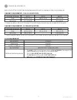
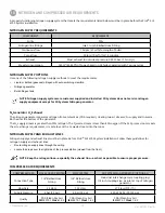
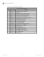
SLS 6100 TRANSFORMER REQUIREMENTS
If the facility does not have 208 VAC, 3-phase, 50/60 Hz, 10 kVA power, a customer-supplied step-up or step-down transformer is
required .
3D Systems stocks the following transformers:
DESCRIPTION
3D SYSTEMS PART NO .
Transformer, 230-250 Volt to 208VAC, 10kVA, 60Hz, 3PH
134005
Transformer, 460-500 Volt to 208VAC, 10kVA, 60Hz, 3PH
134006
Transformer, 385-415 Volt to 208VAC, 10kVA, 50Hz, 3PH (EU Version)
75-0265
•
If you purchase a transformer from a supplier other than 3D Systems, specify a “wye-to-delta” primary-to-secondary config-
uration .
•
Connect the transformer secondary neutral to the transformer secondary ground .
Caution: Do not connect the transformer secondary neutral to the printer ground.
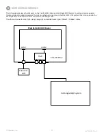
Refer to the ProX
®
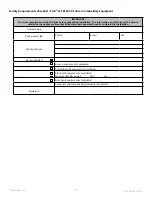
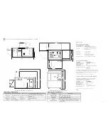
SLS 6100 3D Printer Facility Requirements Poster and SLS Single MQC System Facility Requirements Poster
for visual layouts of the electrical connections .
NOTE: Please contact your local electrician to verify that your facility meets/has met its required local electrical
code .
NOTE: The ProX® SLS 6100 is designed to be connected to primary AC power directly from the facility’s power
circuit to the machine’s input power line filter. This task must be performed by a qualified electrician. The
facility’s power circuit must have a 50A branch protective circuit breaker or fused disconnect with lockout/
tagout capabilities .
ProX
®
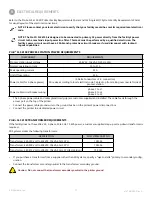
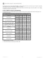
SLS 6100 PROCESS STATION POWER REQUIREMENTS
COMPONENT
REQUIREMENTS
Process station input voltage
208 VAC, 10kVA, 50/60 Hz, 3PH
Normal operating current
10 to 21 A
Peak operating current
25 A
On/Off fuse rating
35 A
Power cable (for 3-phase power)
(3 Delta Cond P .E . connection)
Wire size according to local electrical code . Cable drop from ceiling over rear-left side of
process station
Power cable circuit breaker wiring
phase 1 to L1
phase 2 to L2
phase 3 to L3
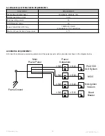
•
The 3-phase power cable and cable gland (cord grip) are customer-supplied and installed . The cable feeds through the
access port on the top of the printer .
•
Connect the power cable ground wire to the ground bus bar in the printer’s power disconnect box .
•
Connect the printer to a dedicated power circuit .
9
ELECTRICAL REQUIREMENTS