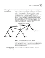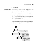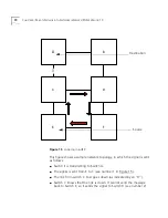
Hierarchy in an E-IISP Network
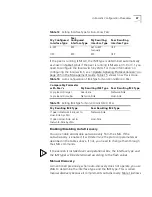
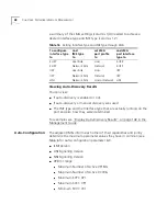
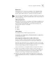
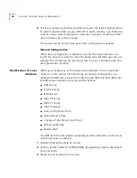
57
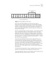
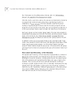
Figure 12
Fields Available for Switch Address
Each of the fields RD and AREA is two bytes long and a byte is
represented by two hexadecimal digits 0-F so that fields RD and AREA
together are represented by eight hexadecimal digits. These eight digits
represent the location of a device in the network tree hierarchy. The
device is assigned an ATM address with these digits set according to its
position in the hierarchy.
The system works as follows: The left-most digit
—
the first digit in the RD
field
—
represents the top level of the network hierarchy. This digit is
assigned to those switches that are connected as roots in the network,
for example, A, B, and C in Figure 10. The ATM address of these switches
has A, B, or C as the first digit in the RD field and the remaining 7 digits
are zero (putting “*” as the second digit has the same effect
—
it marks
the end of the significant digits).
The second digit identifies all switches that are attached to the root
switches where the first digit is retained in the address to point to the
root switch, for example, A1 and A2 in Figure 10. The digit A points to
the root A, and the digits 1 and 2 denote the second-level switches
attached to the root A. Note that because a hexadecimal digit can range
from 0 to F, each switch can have up to 15 second level switches
emanating from it. These digits are used in the ATM address assigned to
these switches.
The third digit identifies switches that are attached to the second-level
switches in a similar fashion and similarly up to the eighth digit.
Using eight digits with values from 0 to F allows a tree structure of up to
eight levels where each node can have 15 branches.
AFI
I C D
DFI
A A
R S R V D
R D
A R E A
Bytes Available for User
Definition
Each line represents one byte
Содержание CoreBuilder 7000
Страница 12: ......
Страница 30: ...30 CHAPTER 1 ATM NETWORK BASICS...
Страница 32: ...32 CHAPTER 1 ATM NETWORK BASICS...
Страница 34: ...34 CHAPTER 1 ATM NETWORK BASICS Figure 8 LANE Network over WAN...
Страница 96: ...96 CHAPTER 4 PRIVATE NETWORK TO NETWORK INTERFACE PNNI VERSION 1 0...
Страница 184: ...184 CHAPTER 7 LAN EMULATION VERSIONS 1 0 AND 2 0...
Страница 206: ...206 CHAPTER 9 DEVICE MANAGEMENT...
Страница 222: ...222 APPENDIX A TECHNICAL SUPPORT...
Страница 234: ...234 APPENDIX B PROTOCOLS AND INTERFACES...
Страница 238: ...238 APPENDIX C COREBUILDER 7000 FAMILY ATM SWITCH SPECIFICATIONS...
Страница 242: ...242 APPENDIX D SAFETY INFORMATION...

