

Physical-Link Failure Indicator
129
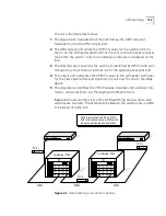
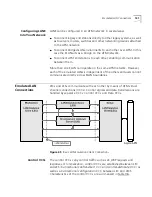
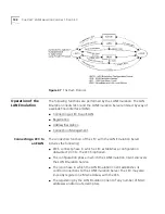
The recovery process proceeds in the following steps:
1
The link failure is detected and the system software is notified.
2
The ILMI service deletes ATM addresses of devices on the failed link which
were registered by ILMI.
3
The call control software releases any calls which were being carried by
the affected link.
4
PNNI, when enabled, sends a port-down notification to PTSE.
5
The RELEASE message transmitted towards the LEC that initiated the call
causes the network to re-establish a virtual channel over an alternate
route.
6
The call is re-established over the new virtual channel.
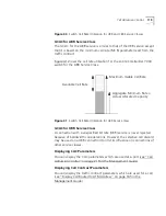
Link Failure Detection
Previously, link failure was detected by the switch based on ATM
signaling, a relatively slow process. Version 4.0 features a new
hardware-based link-failure detection mechanism. With this new
mechanism, the CoreBuilder 7000 initiates failover immediately after
physical link failure.
The link-failure detection hardware has the following properties:
Detects a link failure much faster than detection methods based on
ATM protocols like signaling or ILMI.
Reliable failure detection - fewer false alarms
Sensitivity of the detection is controllable
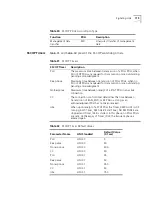
Link-Failure Detection
Sensitivity Control
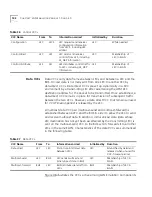
Sensitivity control of the link failure detection mechanism allows you to
balance certainty of detection with speed of detection. On the one hand,
you want to increase detection time to eliminate false link failures; on the
other hand, a link failure needs to be reported with minimum delay to
re-establish the interrupted calls.
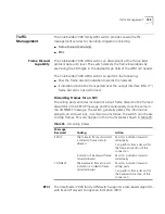
Through the LMA, you specify the length of time the detection
mechanism can use to verify a link failure before reporting it to the
system software (see “Update Link-Failure Indicator Sensitivity” on page
126 in the Management Guide). This choice affects both speed of
detection and certainty of detection as shown in Table 34.
Содержание CoreBuilder 7000
Страница 12: ......
Страница 30: ...30 CHAPTER 1 ATM NETWORK BASICS...
Страница 32: ...32 CHAPTER 1 ATM NETWORK BASICS...
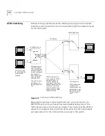
Страница 34: ...34 CHAPTER 1 ATM NETWORK BASICS Figure 8 LANE Network over WAN...
Страница 96: ...96 CHAPTER 4 PRIVATE NETWORK TO NETWORK INTERFACE PNNI VERSION 1 0...
Страница 184: ...184 CHAPTER 7 LAN EMULATION VERSIONS 1 0 AND 2 0...
Страница 206: ...206 CHAPTER 9 DEVICE MANAGEMENT...
Страница 222: ...222 APPENDIX A TECHNICAL SUPPORT...
Страница 234: ...234 APPENDIX B PROTOCOLS AND INTERFACES...
Страница 238: ...238 APPENDIX C COREBUILDER 7000 FAMILY ATM SWITCH SPECIFICATIONS...
Страница 242: ...242 APPENDIX D SAFETY INFORMATION...


