


5
Installation Outline
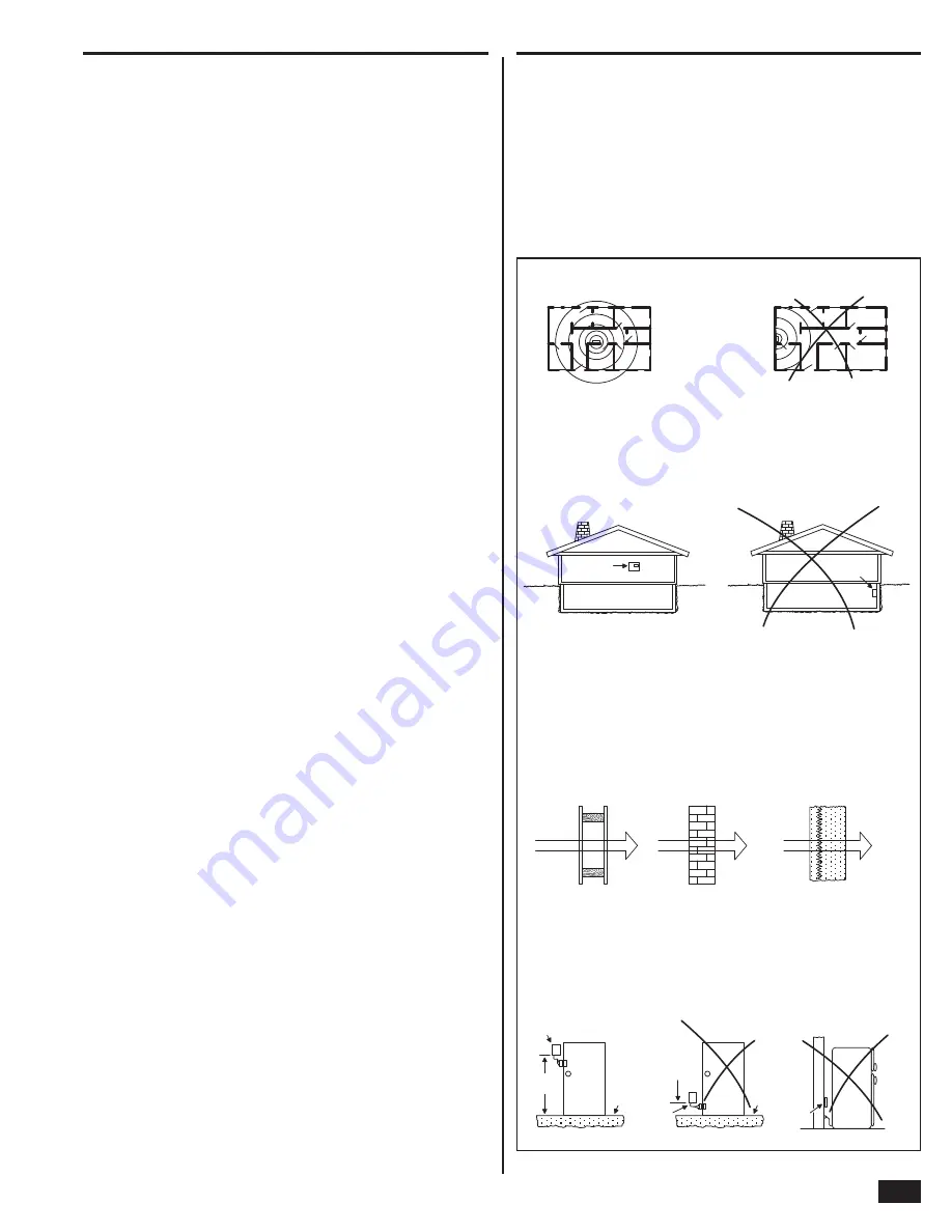
Wireless Installation Tips
The following outline is intended to guide the installing alarm
dealer through the complete installation of a Go!Control system.
Use the following outline in conjunction with this copy of the
Installation Instructions to guide you through the installation.
1.
Unpack the system. Identify the system components.
2.
Plan the installation by creating an installation fl oor plan.
Determine the best centralized location for the Control Panel.
Decide on where the wireless sensors will be installed.
3.
Identify an
un-switched
120 VAC power source for plugging
in the Control Panel’s power supply.
4.
Identify or install a U.S.O.C. RJ31X telephone jack for
connection of the Control Panel’s communicator.
5.
Use the Control Panel’s mounting plate as a template to mark
the mounting location for the Control Panel. Mark any drywall
cutouts behind the mounting plate required for the installation
and make the cutouts.
6.
Attach the mounting plate to the wall using three screws.
7.
Install each of the system’s wireless sensors. If either of the
two hardwire loops are going to be used, install the contacts
and route the loop wire to the Control Panel’s wall cutout. Use
the log in the quick programming guide to document each
sensor’s ID number and location.
8.
Install the optional remote sounder, and route the connection
wire to the Control Panel’s wall cutout.
9.
Route the telephone line from the RJ31X jack to the Control
Panel’s wall cutout.
10.
Using the “third hand” strap, hang the Control Panel on the
mounting plate in preparation for wiring.
11.
Connect all wiring to the Control Panel’s terminal block.
12.
Plug the telephone line into the Control Panel’s telephone
jack.
13.
Plug the backup battery connector into the connector on the
Control Panel’s circuit board.
14.
Swing the Control Panel up, placing the bottom over the lip of
the mounting bracket. Push the top of the Control Panel into
the mounting bracket until it snaps into place, then secure it
with the retaining screw.
15.
Plug the power supply into the
un-switched
120 VAC wall
outlet.
16.
Program the system as described in this manual and mark
the check boxes in the Operation and User’s Guide to indicate
any custom setup to the subscriber.
17.
Test the system as described in this manual.
18.
Instruct the subscriber on the system operation and provide
the Operation and User’s Guide to the subscriber.
When installing any wireless system, certain limitations must
be considered. Low power wireless transmitter signals will
not
broadcast equally through all types of construction materials. The
Control Panel contains a very sensitive receiver that should allow
placement of transmitters in almost all locations.
Here are some general wireless guidelines that should be reviewed
before beginning the installation. Follow these tips to create the
best possible functioning wireless installation.
WRONG!
RIGHT
CENTRALLY LOCATE
CONTROL PANEL
SENSORS AT THE OTHER END OF
HOUSE MIGHT BE TOO FAR AWAY
BASEMENT
BASEMENT
CONTROL
PANEL
CONTROL
PANEL
RIGHT
WRONG!
LOCATING CONTROL PANEL BELOW
EARTH LEVEL WILL IMPAIR RANGE
MOUNT CONTROL PANEL AS HIGH ABOVE
EARTH LEVEL AS PRACTICAL
90% - 100%
OF FULL POWER
65% - 95%
OF FULL POWER
10% - 70%
OF FULL POWER
WALLBOARD AND
WOOD STUDS
CONCRETE WITH STEEL
REINFORCEMENT OR
METAL LATH AND PLASTER
LIGHT CONCRETE
OR BRICK
CONTROL PANEL LOCATION RELATIVE TO SENSORS
CONTROL PANEL LOCATION HEIGHT
SENSOR SIGNAL LOSS THROUGH MATERIALS
LOCATION OF SENSORS
SENSOR
Concrete
slab
floor
DOOR
Concrete
slab
floor
DOOR
Less
than
3 ft.
above
slab
Min.
3 ft.
RIGHT
WRONG!
Wall
WRONG!
Large
metal
appliance
(refrig.)
SENSOR
SENSOR
Figure 6. Wireless Installation Tips
Содержание GO!control 2GIG-CNTRL2
Страница 1: ...Wireless Security System Installation Programming Instructions 2GIG CNTRL2 2GIG CP2...
Страница 48: ...46 Notes...
Страница 49: ...47 Notes...
Страница 52: ...v1 9 233497 E Copyright 2012...