


2
Introduction
The Go!Control Security System represents a signifi
cant
advancement in fully supervised wireless security systems. The
security system Control Panel incorporates many advanced
and sophisticated features. The system can be expanded and
customized to fi t the installation’s specifi c needs.
Designed to meet or exceed the requirements for ETL Listed
residential security installations, the system also conforms to the
Security Industry Association’s Control Panel Standard ANSI/SIA
CP-01-2010.
✓
NOTE:
Failure to install the Control Panel and accessories in
accordance with ETL requirements listed in this manual voids
the ETL listing mark assigned by Intertek.
Many insurance companies offer discounts on homeowners’ and
renters’ policies when a security system is installed. Discount
credits vary with different companies and generally increase in
savings with an increase in the level of protection. Inform the user
to ask their insurance agent about savings available.
This security system is
ETL Listed. For an ETL smoke alarm
system, there must be at least one smoke detector programmed
into the Control Panel to meet National Fire Protection Association
(NFPA) Rule 72-Chapter 2, and UL 217 requirements. Many
insurance companies require meeting these requirements to
qualify for a discount. For an ETL smoke alarm system, use only
approved model smoke detectors with this Control Panel.
✓
NOTE:
Some cities and municipalities may require an alarm
system permit. Check with the local authorities before installing
this system.
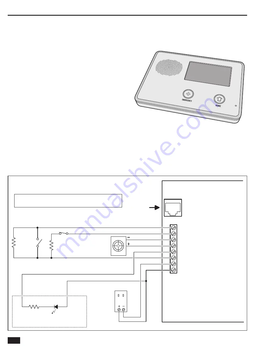
NO
R
MALLY CLO
S
ED
CONTACT
NO
R
MALLY
OPEN
CONTACT
2
.
2
K
END-OF-LINE
R
E
S
I
S
TO
RS
A
R
E
OPTIONAL ON HA
R
DWI
R
E LOOP
S
2
.
2
K
HA
R
DWI
R
E LOOP
S
CAN
B
E P
R
O
GR
AMMED
A
S
NO
R
MALLY OPEN O
R
CLO
S
ED
S
UPE
R
VI
S
ED
B
ELL OUTPUT
6-1
2
VDC @ 1
2
0
m
A MAXIMUM
TELEPHONE LINE
F
R
OM
R
J
3
1X
TELEPHONE JACK
PIEZO
S
I
R
EN
1
2
0 VAC 60 HZ
PLU
G
-IN 14 VDC
1.7 AMP
S
WITCHIN
G
POWE
R
S
UPPLY
1 K
LED
OPEN COLLECTO
R
OUTPUT
2
50
m
A @ 16 VDC MAXIMUM
EXAMPLE HOOKUP
S
HOWIN
G
AN A
R
MED LED,
THE OPEN COLLECTO
R
OUTPUT CAN
B
E P
R
O
GR
AMMED
TO ACTIVATE DU
R
IN
G
VA
R
IOU
S
CONDITION
S
UL NOTE
:
WI
R
ING FO
R
ALL WI
R
ED
S
EN
S
O
RS
AND ANNUNCIATO
RS
MU
S
T U
S
E
UL LI
S
TED LOW VOLTAGE CL2X O
R
BETTE
R
G
R
ADE WI
R
E.
S
EN
S
O
R
AND DI
S
PLAY
VOLTAGE
S
MU
S
T COMPLY WITH CLA
SS
2 LOW VOLTAGE
R
EQUI
R
EMENT
S
.
OB
S
E
R
VE
POLA
R
ITY WHEN
CONNECTING THE
POWE
R
S
UPPLY !!!
CONT
R
OL PANEL
TELEPHONE
JACK
8
- HA
R
DWI
R
E LOOP
2
7 - HA
R
DWI
R
E LOOP 1
6 -
B
ELL (-)
5 -
B
ELL (+)
4 - OPEN COLLECTO
R
OUTPUT
3
-
GR
OUND
2
- 14 VDC POWE
R
INPUT (-)
1 - 14 VDC POWE
R
INPUT (+)
NOTE: TERMINAL 1 WILL ONLY
PROVIDE DC POWER WHEN
THE CONTROL PANEL'S
POWER SUPPLY IS CONNECTED
TO AN AC POWER SOURCE
ALL OUTPUT
VOLTAGES
ARE CLASS 2
R
EFE
R
ENCE ONLY -
R
EFE
R
TO ADDENDUM 230373 FO
R
P
R
OPE
R
IN
S
TALLATION AND WI
R
ING DIAG
R
AM
Figure 2. Control Panel Wiring Diagram
2GIG-CNTRL2
(2GIG-CP2)
Содержание GO!control 2GIG-CNTRL2
Страница 1: ...Wireless Security System Installation Programming Instructions 2GIG CNTRL2 2GIG CP2...
Страница 48: ...46 Notes...
Страница 49: ...47 Notes...
Страница 52: ...v1 9 233497 E Copyright 2012...


